Eureka AIR delivers breakthrough ideas for toughest innovation challenges, trusted by R&D personnel around the world.

A reinforced concrete composite beam and steel pipe column seismic connection structure

A technology for reinforced concrete and connecting structures, which is applied in earthquake resistance, building components, building structures, etc., can solve problems such as cumbersome construction, and achieve the effect of reducing the amount of on-site work, avoiding the binding of steel bars, and shortening the construction period.

Inactive Publication Date: 2017-01-11
HUBEI HONGSHUN STEEL STRUCTURE MFG
View PDF5 Cites 0 Cited by
  • Summary
  • Abstract
  • Description
  • Claims
  • Application Information

AI Technical Summary

Problems solved by technology

In the prior art, steel pipe columns and reinforced concrete beams are mostly connected by interspersing steel bars at the joints or constructing reinforced concrete ring beams. The construction of this joint form is cumbersome and only suitable for cast-in-place concrete beams. Therefore, it is necessary to develop a Easy-to-construct connection structure

Method used


Image

  • A reinforced concrete composite beam and steel pipe column seismic connection structure
  • A reinforced concrete composite beam and steel pipe column seismic connection structure
  • A reinforced concrete composite beam and steel pipe column seismic connection structure

Examples


Embodiment 1

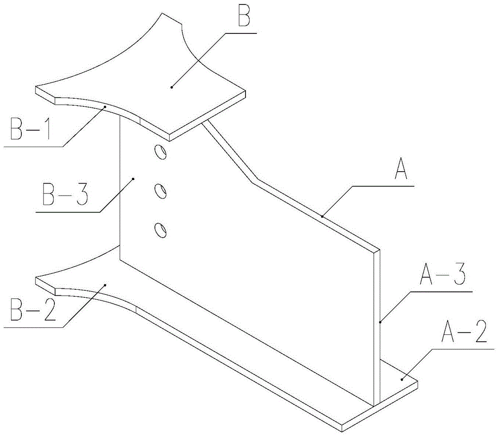
[0030] According to the above-mentioned embodiment, the beam-end section steel connector A of the beam-column transition member correspondingly welded on the upper and lower longitudinal steel bars 4-1 and 4-2 of the prefabricated reinforced concrete lower beam 2 reinforcement cage 4 is an inverted T Sectional steel connector, the upper longitudinal reinforcement 4-1 of the steel cage 4 of the prefabricated reinforced concrete lower beam 2 is welded to the upper flange plate B-1 of the H-shaped steel connector B at the column end, and the lower longitudinal reinforcement 4-2 is connected to the inverted T-shaped steel The bottom surface A-2 of the head is corresponding to welding, and the rest are as described in the detailed description.

Embodiment 2

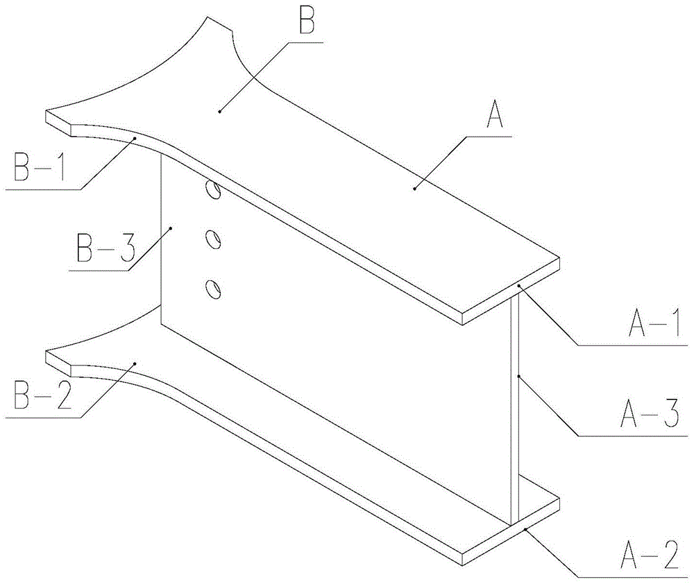
[0032] According to the above-mentioned embodiment, the beam-end section steel connector A of the beam-column transfer member correspondingly welded between the upper and lower longitudinal reinforcement bars 4-1 and 4-2 of the prefabricated reinforced concrete lower beam 2 reinforcement cage 4 is an H-section steel Connectors, the upper and lower longitudinal steel bars 4-1, 4-2 of the reinforcement cage 4 of the prefabricated reinforced concrete lower beam 2 are respectively connected to the top and bottom surfaces A-1, A-2 corresponds to welding, and the rest are as described in the detailed description.


PUM


Abstract

The invention discloses an anti-seismic connection structure between a reinforced concrete composite beam and a steel pipe column, which belongs to the field of industrialized assembled building structures. In this design, the joints of the steel pipe column are provided with circular positioning connectors, and the beam-to-column transfer member consists of a beam-end steel connector and a steel pipe column. The H-shaped steel connector at the column end is composed of the beam-end steel connector correspondingly connected between the upper and lower longitudinal steel bars of the prefabricated reinforced concrete lower beam reinforcement cage, and the poured concrete is connected with the lower beam; the integrally connected beam- The column-end section steel connector of the column transfer member is correspondingly connected with the steel pipe column node ring positioning connector, and the concrete is poured along the beam-column transfer member between the upper longitudinal reinforcement and the connection node with the steel pipe column to form a composite beam Integral connection with the steel column pipe, the invention converts the connection between the reinforced concrete structure and the steel structure into a mature steel structure bolt welding connection form through the beam-column adapter, which is safe and reliable, and meets the requirements of "strong columns and weak beams, strong nodes and weak beams". Components" seismic requirements.

Description

technical field [0001] The invention relates to an anti-seismic connection structure of a reinforced concrete composite beam and a steel pipe column, which belongs to the field of industrialized assembled building structures. Background technique [0002] Due to their excellent performance characteristics, steel pipe columns are widely used in buildings, especially some high-rise buildings. Such buildings have higher seismic requirements for buildings, and need to meet the seismic design requirements of strong columns, weak beams, strong joints and weak components. The combination of reinforced concrete composite beams and steel pipe columns meets the inherent requirements of "building industrialization" prefabrication. If the seismic problem of the connection between reinforced concrete beams and steel pipe columns is solved, it will have positive significance for promoting "building industrialization". In the prior art, steel pipe columns and reinforced concrete beams are ...

Claims


Application Information

Patent Timeline
Patent Type & Authority Patents(China)
IPC IPC(8): E04B1/58E04B1/98
Inventor 吴顺红黄胜周少勋王少重
Owner HUBEI HONGSHUN STEEL STRUCTURE MFG
Why Eureka
Eureka Blog
Learn More