
Air energy generating set

A generator set, gas energy technology, applied in the direction of machine/engine, liquid fuel engine, rotary piston engine, etc., can solve the problem of compressed gas not being completely discharged in time, energy consumption, energy consumption and temperature rise, etc., to alleviate the problem. Smog city problem, solve energy crisis problem, no effect of emissions and pollution

Inactive Publication Date: 2015-04-08
程群英
View PDF0 Cites 0 Cited by
  • Summary
  • Abstract
  • Description
  • Claims
  • Application Information

AI Technical Summary

Problems solved by technology

Its operation process still needs other raw materials as a supplement, so the exchange will still cause pollution
In order to achieve air compression, the traditional piston air compressor has the following disadvantages: the spring force of the suction valve is too large, and the suction valve will be closed in advance, resulting in insufficient suction
If the spring force is too small, the gas valve will be closed late, and the gas in the cylinder will flow back into the suction chamber.
If the spring force of the exhaust valve is too large, the exhaust valve will be closed early. When the exhaust is completed, the gas pressure in the compression chamber of the cylinder will increase, and the compressed gas cannot be completely discharged in time, resulting in the gas in the clearance volume at the end of compression. As the pressure increases, the volumetric flow rate of the compressor decreases, and the energy consumption increases; if the spring force of the exhaust valve is too small, it will cause the exhaust valve to be closed late, so that when the piston in the cylinder goes down, the exhaust valve is not closed when the piston in the cylinder is in the suction state. At this time, the cylinder is in a relatively vacuum state, and the inhaled gas produces a cross-flow, resulting in a decrease in volumetric flow rate, and an increase in energy consumption and temperature.

Method used


Image

  • Air energy generating set

Examples


Embodiment Construction

[0014] The present invention will be further described below in conjunction with accompanying drawing.

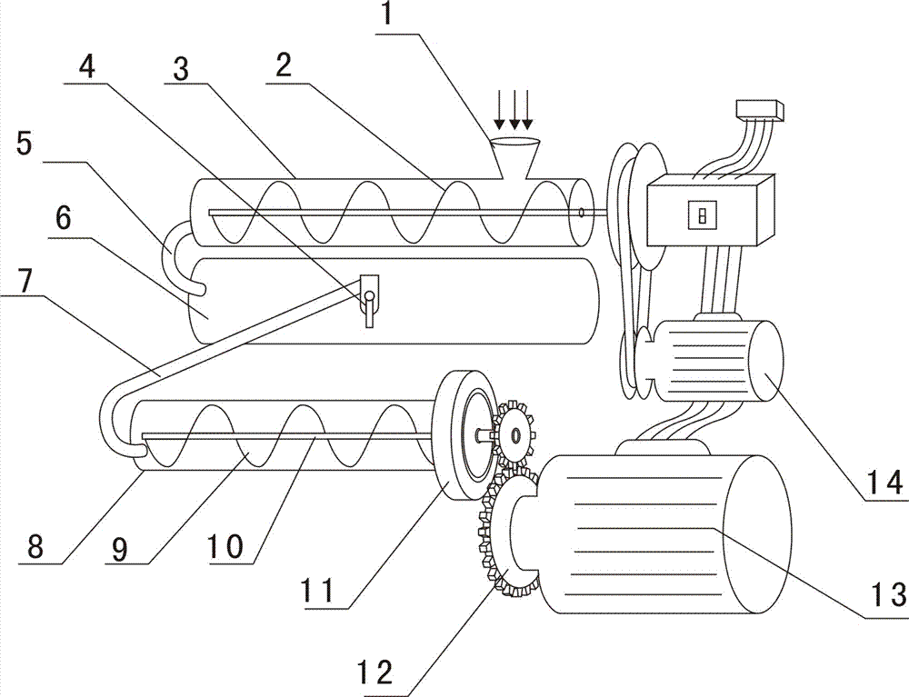
[0015] The air energy generator set includes a motor 14, the transmission shaft of the motor is connected with the driving shaft of the belt pulley, and the driven wheel shaft is connected with the screw shaft of the air compression pipe 3. The drive shaft is used to drive the driving wheel shaft to rotate, thereby driving the driven wheel shaft and the screw shaft to rotate. Through the belt drive, the impact can be eased and the vibration can be absorbed, so the screw shaft runs smoothly and the noise is small. The screw blade 2 is welded on the screw shaft. The helical blades are distributed on the helical shaft in the form of a cylindrical helix, and the top view of the helical blades is circular.

[0016] An air funnel 1 is provided above the side of the air compression tube close to the pulley. The air funnel is a conical structure and is arranged on the side close...


PUM


Abstract

The invention relates to the technical field of motor, and concretely relates to an air energy generating set. the air energy generating set comprises an electromotor, the electromotor is connected to an air compression pipe through a belt pulley, the air compression pipe is connected to a high pressure air bottle through an air inlet pipe for providing gas source to the high pressure air bottle; the high pressure air bottle is connected to a pneumatic spiral pipe, flywheels are arranged outside the pneumatic spiral pipe, the flywheel is connected to a gear, power output is carried out to the generator through the gear, and kinetic energy is transformed to electric energy. From the aspect of effect, the air energy generating set has the advantages of zero discharge, zero pollution, natural cleaning, green environmental protection, less land occupation, low investment cost, short period of plant construction and wide usage, and can transform air energy to electric energy. The air energy generating set is suitable for construction of large region in our country, and energy crisis problem can be effectively solved.

Description

technical field [0001] The invention relates to the technical field of generators, in particular to an air energy generator set. Background technique [0002] Stable, reliable and clean energy supply is the guarantee of human civilization, economic development and social progress. However, the massive consumption of fossil fuels not only makes human beings face the pressure of resource depletion, but also feels the threat of environmental degradation. The current stage is a stage of accelerated development of science and technology, economy, and society, and it is also a transition from fossil fuels to an energy era with sustainable utilization capabilities. [0003] People often regard wind power as one of the cleanest and non-polluting power generation technologies. As a clean and renewable energy source, wind energy is inexhaustible; it can be taken locally without transportation; it is widely distributed and used in a scattered manner; it does not pollute the envir...

Claims


Application Information

Patent Timeline
Patent Type & Authority Applications(China)
IPC IPC(8): F01C13/00F01C1/107F04C23/02F04C18/107
CPCF01C13/00F01C1/107F04C18/107F04C23/02
Inventor 任正才
Owner 程群英
Learn More