Zoned and layered thin combustion engine control device

A lean combustion, zoning and layering technology, applied to combustion engines, internal combustion piston engines, engine components, etc., can solve problems such as high fuel consumption, increased pumping loss, and increased pumping loss, and improve thermal power conversion rate, reduce pumping loss, and reduce the effect of pumping loss

Inactive Publication Date: 2015-04-08
李伟
View PDF5 Cites 4 Cited by
  • Summary
  • Abstract
  • Description
  • Claims
  • Application Information

AI Technical Summary

Problems solved by technology

[0002] At present, the most widely used automobile engine is the reciprocating piston engine, which achieves fuel economy through turbocharging at high speed and heavy load, but fails to achieve fuel economy at idle speed and light load, so it is used in the market. Significantly high fuel consumption when driving at low speeds
[0003] The reasons are as follows: (1) When the throttle valve is completely closed at idle speed, only a small amount of air enters the cylinder through the idle passage of the throttle valve, so that a large vacuum is formed when the air is inhaled, which will inevitably reduce the energy consumed by the intake air. increase, increasing the pumping loss; at the same time, because the vacuum degree of the intake pipe is very large at this time, when the intake valve is opened, the pressure in the cylinder is higher than the pressure of the intake pipe, and the exhaust gas expands into the intake pipe. During the suction stroke, The exhaust gas and the new mixed gas are sucked into the cylinder at the same time. In order to ensure the normal combustion of the mixed gas diluted by the exhaust gas, more fuel must be supplied to enrich the mixed gas, which will inevitably increase the fuel consumption; (2) under small load At this time, the opening of the throttle valve is very small, so that a large vacuum is formed when the intake valve is opened. When the intake valve is opened, the pressure in

Method used


Image

  • Zoned and layered thin combustion engine control device
  • Zoned and layered thin combustion engine control device
  • Zoned and layered thin combustion engine control device

Examples


Example Embodiment

[0036] In order to deepen the understanding of the present invention, the present invention will be further described below with reference to the accompanying drawings and embodiments. The embodiments are only used to explain the present invention and do not limit the protection scope of the present invention.
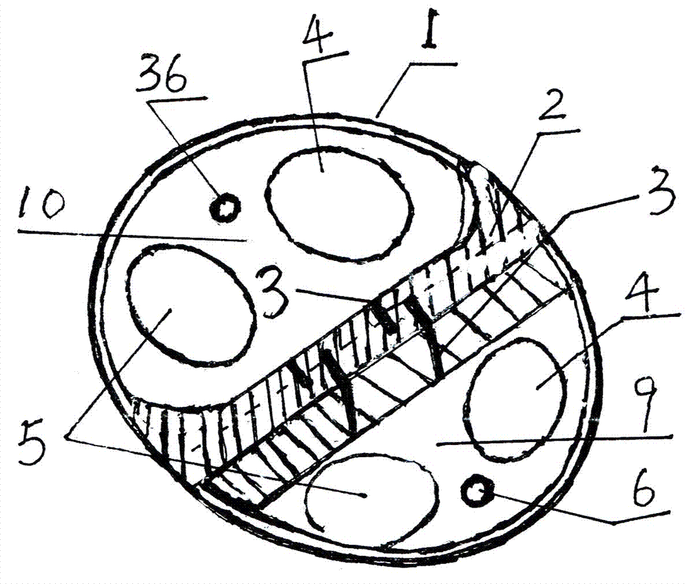
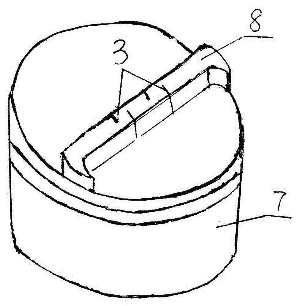
[0037] like Figure 5 As shown, a zoned stratified lean burn engine control device includes a cylinder 42 and a turbocharger 11 and an exhaust gas storage container 12 connected to its exhaust port in sequence, and the exhaust gas storage container 12 is connected to the cylinder intake through an exhaust gas return pipe 17. On the air pipe 20, so as to realize the recycling of exhaust gas; the cylinder 42 is connected to the cylinder head 1 at its top position; the control device also includes an electronic control unit 28 and an electromagnetic controller connected to it; the cylinder head 1 is provided with a cylinder head partition Plate 2, the top position of the ...


PUM


Abstract

The invention discloses a zoned and layered thin combustion engine control device. The zoned and layered thin combustion engine control device comprises an electromagnetic controller, as well as a gas-in changeover valve I, a gas-in changeover valve II, an oil sprayer I and an oil sprayer II, which are respectively connected to an electronic control unit, wherein a combustion chamber is separated into a small combustion zone and a large combustion zone; cylinder gas-in pipes are respectively connected to the large combustion zone and the small combustion zone, a cylinder gas-in pipe shunting plate is arranged in each cylinder gas-in pipe, and each cylinder gas-in pipe is divided into a large gas-in pipe and a small gas-in pipe. As engine zoned and layered combustion is realized, when an automobile is at idle speed or carries small load or medium load, the combustion efficiency of fuel oil in the engine is improved, the oil consumption and the emitted exhaust gas of the engine are reduced, and the safe use of the engine during large load is ensured. Therefore, the environmental-friendly performance of the automobile during running is improved, and the use cost is reduced.

Description

technical field [0001] The invention relates to the technical field of engines, in particular to a control device for a partitioned and stratified lean combustion engine. Background technique [0002] At present, the most widely used automobile engine is the reciprocating piston engine, which achieves fuel economy through turbocharging at high speed and heavy load, but fails to achieve fuel economy at idle speed and light load, so it is used in the market. The fuel consumption is obviously too high when driving at low speed in the area. [0003] The reasons are as follows: (1) When the throttle valve is completely closed at idle speed, only a small amount of air enters the cylinder through the idle passage of the throttle valve, so that a large vacuum is formed when the air is inhaled, which will inevitably reduce the energy consumed by the intake air. increase, increasing the pumping loss; at the same time, because the vacuum degree of the intake pipe is very large at this...

Claims


Application Information

Patent Timeline
IPC IPC(8): F02B23/08F02M25/07F02F1/18F02F3/00F02M26/20F02M26/21F02M26/38F02M26/44
CPCY02T10/12
Inventor 汪辉
Owner 李伟
Why Eureka
Try Eureka