Infrared nondestructive testing and imaging method based on array laser source and used for structure surface cracks

An infrared non-destructive testing and structural surface technology, applied in material defect testing and other directions, can solve the problems of slow detection speed and complex system, and achieve the effect of intuitive results, high sensitivity and easy operation.

Inactive Publication Date: 2015-04-08
XI AN JIAOTONG UNIV
View PDF3 Cites 17 Cited by
  • Summary
  • Abstract
  • Description
  • Claims
  • Application Information

AI Technical Summary

Problems solved by technology

However, the current laser infrared detection uses a single laser beam to cover a small area, and obtains the overall image of the cracks on the surface of the structure through mechanical point-by-point scanning, so there are disadvantages such as relatively complicated system and slow detection speed.

Method used


Image

  • Infrared nondestructive testing and imaging method based on array laser source and used for structure surface cracks
  • Infrared nondestructive testing and imaging method based on array laser source and used for structure surface cracks
  • Infrared nondestructive testing and imaging method based on array laser source and used for structure surface cracks

Examples


Embodiment Construction

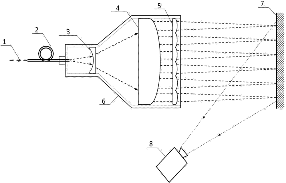
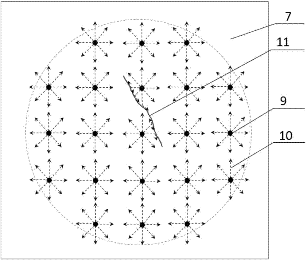
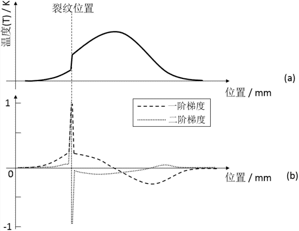
[0020] like figure 1 and figure 2 As shown, the measurement principle of the method of the present invention is: use a high-energy optical fiber to deliver the laser light to the vicinity of the detection object without moving the laser, and the laser beam after passing through the beam expander collimating lens and the focusing lens array is on the test piece 7 The surface and the area with a diameter of several centimeters form a plurality of uniformly distributed array laser point heat sources 9 with a radius of less than 1 millimeter. When the thermal energy 10 radiated from the laser point source diffuses to the vicinity of the crack 11, it will be hindered by it and cannot continue to propagate forward. It can only propagate along one side of the crack and diffuse from its two ends and bottom to the other side of the crack. Therefore, when the thermal energy diffuses to the vicinity of the crack for a period of time, not only will a large temperature difference (gradie...


PUM

PropertyMeasurementUnit
radiusaaaaaaaaaa
diameteraaaaaaaaaa

Abstract

The invention discloses an infrared nondestructive testing and imaging method based on an array laser source and used for structure surface cracks. The method comprises the following steps: expanding the beam of a laser source generated by a pulse laser device into a collimation laser beam with the diameter of several centimetres by virtue of a laser beam expander at first, and then focusing the laser beam onto the surface of the tested piece by virtue of m*n array convex lenses to form array laser spots with radiuses of less than 1mm and uniformly distributed, and then monitoring the temperature field distribution change condition of the surface of the tested piece irradiated by the array pulse laser source by using an infrared camera; when cracks exist in the irradiated area of the surface of the tested piece, the cracks block the diffusion of the heat of the laser irradiation on the surface, thus forming a high temperature difference at the both sides of each crack. Therefore, the cracks on the surface of the tested piece can be tested and imaged through the temperature gradient field of the irradiated area. The method disclosed by the invention has the advantages of being simple in system structure, easy to realize and operate, high in testing speed, high in sensitivity, intuitive in result, capable of realizing remote testing, and the like.

Description

technical field [0001] The invention relates to a long-distance nondestructive detection and imaging method for structural surface cracks, in particular to an infrared nondestructive detection and imaging method for structural surface cracks based on an array laser source. Background technique [0002] Mechanical mechanisms, especially some important structures, are usually subjected to complex loads during use or operation, and are prone to cracks inside the structure, especially fatigue cracks and stress corrosion cracks on the surface of the structure. The existence of these cracks will not only greatly reduce the strength of the structure, but also cause great safety hazards. [0003] At present, the most commonly used non-destructive inspection methods for structural surface cracks are ultrasonic testing (UT), eddy current testing (ECT), magnetic particle testing (MT) and penetrant testing (PT). At present, although ultrasonic testing has a wide range of applications, ...

Claims


Application Information

Patent Timeline
Patent Type & Authority Applications(China)
IPC IPC(8): G01N25/72
Inventor 裴翠祥陈振茂蔡文路杨桂才
Owner XI AN JIAOTONG UNIV
Why Eureka
Try Eureka