
Injection-molding shock absorption rotor

A technology of rotor and shock-absorbing rubber, which is applied in the direction of magnetic circuit rotating parts, manufacturing motor generators, electrical components, etc., can solve the problems of motor power and efficiency that are difficult to meet the requirements, waste of human resources, abnormal motor noise, etc., to achieve Improve the use value and economic benefits, improve the shock absorption effect, and improve the effect of mechanical strength

Inactive Publication Date: 2015-04-08
FGLS ELECTRIC CO LTD
View PDF5 Cites 9 Cited by
  • Summary
  • Abstract
  • Description
  • Claims
  • Application Information

AI Technical Summary

Problems solved by technology

The known defects of this structure are: 1. The magnetic properties of commonly used plastic magnetic materials are not high, and the power and efficiency of the motor are difficult to meet the requirements.
2. The structure needs to be reprocessed many times after injection molding, which wastes a lot of human resources
This structure also has many defects: 1. The processing technology is difficult, the position accuracy cannot be guaranteed, and the rotor balance accuracy after assembly is poor
2. During transportation and loading into the motor, it is easy to bump and cause the magnetic steel to break, and it is easy to have magnetic chips that cause abnormal noise of the motor
3. When the operating environment is bad (the temperature is too high or too low) or the motor is vibrating, it is easy to cause the glue to fail and the magnetic steel to fall off, causing the motor to fail to operate normally or even burn out, resulting in a serious accident

Method used


Image

  • Injection-molding shock absorption rotor
  • Injection-molding shock absorption rotor
  • Injection-molding shock absorption rotor

Examples


Embodiment Construction

[0017] The present invention will be further described below in conjunction with accompanying drawing:

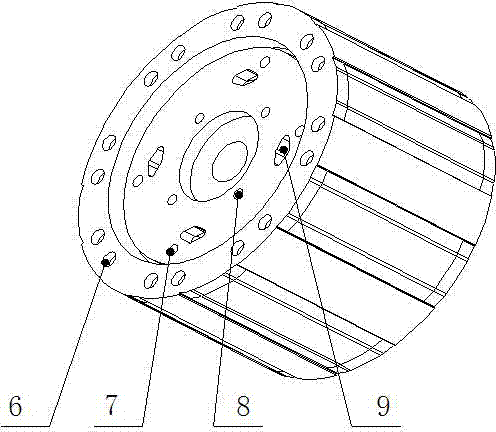
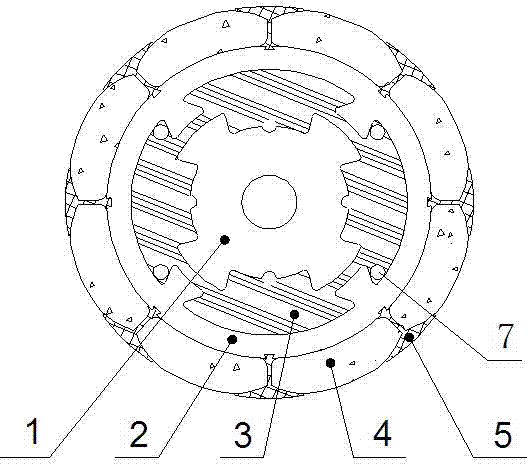
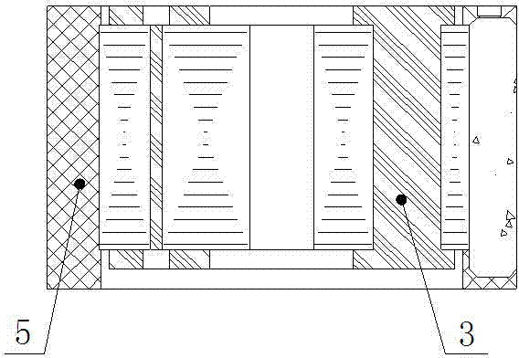
[0018] Referring to the accompanying drawings, an injection-molded shock-absorbing rotor includes a supporting iron core 1 and a magnetic steel 4, and is characterized in that: the outer periphery of the supporting iron core 1 is provided with a shock-absorbing rubber 3, and the outer periphery of the shock-absorbing rubber 3 is provided with a yoke 2 A plurality of magnetic steels 4 are evenly distributed on the periphery of the magnetic yoke 2, and engineering plastics 5 are injected in the gap between the dovetail groove on the magnetic yoke and the magnetic steel and the gap formed between the outer circles of adjacent magnetic steels. A plurality of dovetail grooves 21 are evenly arranged on the outer circle of the magnetic yoke 2, and a plurality of dovetail bosses B22 are evenly arranged on the inner circle of the magnetic yoke 2. Several dovetail bosses A12 ar...


PUM


Abstract

The invention discloses an injection-molding shock absorption rotor which comprises a supporting iron core and magnetic steel, wherein shock absorption rubber is arranged at the periphery of the supporting iron core; a magnetic yoke is arranged at the periphery of the shock absorption rubber; a plurality of pieces of magnetic steel are uniformly distributed at the periphery of the magnetic yoke; engineering plastic is injected into clearances between a dovetail groove in the magnetic yoke and the magnetic steel and clearances formed between the outer circles of the adjacent magnetic steel. The injection-molding shock absorption rotor is ingenious and reasonable in structure and convenient to process; the shock absorption effect is enhanced, the equipment noise generated by motor resonance is avoided, the rotor balance precision is improved, and the mechanical strength of the rotor is improved; the magnetism can be improved by over 30 percent in comparison with a common rotor; the service life is prolonged; the injection-molding shock absorption rotor has extremely high use value and economical benefits.

Description

technical field [0001] The invention relates to the technical field of small motor rotor structures, in particular to an injection molding damping rotor. Background technique [0002] There are generally two types of rotors for small motors in the prior art. The first type is usually directly injection-molded using plastic magnetic materials and a rotating shaft. The known defects of this structure are: 1. The commonly used plastic magnetic material has low magnetic properties, and the power and efficiency of the motor are difficult to meet the requirements. 2. The structure needs to be reprocessed many times after injection molding, which wastes a lot of human resources. The second type uses a magnetic steel structure. Usually, the rotating shaft is first riveted with the rotor core, and then the magnetic steel is bonded to the outer periphery of the iron core with glue. This structure also has many defects: 1. The processing technology is difficult, the position accu...

Claims


Application Information

Patent Timeline
IPC IPC(8): H02K1/22
CPCH02K1/276H02K15/03H02K2201/09
Inventor 陈波环宇平
Owner FGLS ELECTRIC CO LTD
Learn More