Gas purifier

A gas purification device and gas technology, which are used in combination devices, chemical instruments and methods, dispersed particle separation, etc., can solve the problems of difficulty in designing the diameter and length of the separation tank, large volume of the separation tank, and decreased separation efficiency, and reduce oil and water. and solid impurities, reducing the amount of impurities, compact structure

Inactive Publication Date: 2015-04-15
CHINA PETROCHEMICAL CORP +1
View PDF4 Cites 2 Cited by
  • Summary
  • Abstract
  • Description
  • Claims
  • Application Information

AI Technical Summary

Problems solved by technology

When the cyclone is used to purify the compressed gas, if the compressed air enters the separation tank and directly performs cyclone separation on the inner wall of the separation tank, the rotating gas may sweep up the impurities in the lower separator again Inlet and outlet pipelines, and the aspect ratio of the separation tank is relatively high, it is difficult to design the diameter and length of

Method used


Image

  • Gas purifier

Examples


Embodiment 1

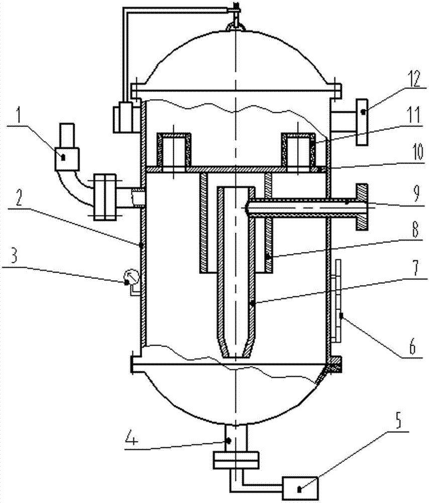
[0016] Refer to attached figure 1 , The gas purification device includes a separation tank, a gas inlet and outlet pipe and a sewage pipe. The separation tank 2 is divided into upper and lower chambers by a partition 10, the upper chamber communicates with the gas outlet pipe 12; the lower chamber is respectively equipped with a safety valve 1, a sewage pipe 4, a liquid level gauge 6 and a pressure measuring device 3 , the sewage pipe 4 is externally connected to the sewage device 5; the partition 10 is processed with a through hole, and a filter 11 is installed on the top, and the lower chamber of the separation tank 2 passes through the through hole on the partition and the filter core of the filter 11. The pores communicate with the upper chamber of the separation tank 2; the lower part of the partition 10 is connected to a round pipe 8, the upper part of the round pipe 8 is sealed and connected with the partition, and the lower part of the round pipe 8 is open; a separatio...

Embodiment 2

[0020] A gas purification device includes a separation tank, a gas inlet and outlet pipe and a sewage discharge pipe. The separation tank is divided into upper and lower chambers by the partition, the upper chamber is connected with the gas outlet pipe; the lower chamber is respectively equipped with a safety valve and a sewage pipe; the partition is processed with through holes, and a filter is installed on the upper part of the separation tank. The lower chamber communicates with the upper chamber of the separation tank through the through holes on the partition and the pores between the filter cores of the filter; the lower part of the partition is connected to a round tube, the upper part of the round tube is sealed with the partition, The lower part is open; a separating circular tube is suspended inside the circular tube; the gas inlet pipe is tangentially inserted into the separating circular tube.

Embodiment 3

[0022] On the basis of Example 2, the upper part of the separating circular tube is cylindrical, and the lower part can be processed into a tapered shape. The cross-section of the gas inlet pipe can be processed into a rectangle or a crescent shape. The round pipe connected to the lower part of the partition can also be processed into a frustum of a cone, that is, an umbrella shape.


PUM


Abstract

The invention discloses a gas purifier, which comprises a separation tank, a gas inlet pipe, a gas outlet pipe and a blowdown pipe. The separation tank is divided into an upper chamber and a lower chamber by a separation plate, wherein the upper chamber communicates with the gas outlet pipe. The lower chamber is separately equipped with a safety valve, the blowdown pipe, a liquid-level meter and a pressure measuring device, wherein the blowdown pipe is externally connected to a blowdown device. Through holes are arranged in the separation plate. A filter is disposed on the upper part of the separation plate. A circular pipe is connected to the lower part of the separation plate. The upper part of the circular pipe is hermetically coupled to the separation plate, and the lower part of the circular pipe is open. A separation circular pipe is hung in the circular pipe. The gas inlet pipe is tangentially inserted into the separation circular pipe. Gas enters the purifier and goes through three processes of hydrocyclone separation, elbow pipe separation, and filter separation. According to the invention, the gas purifier has advantages of impact structure, high separation efficiency and low maintenance efficiency.

Description

technical field [0001] The invention relates to an air purification device, in particular to a gas purification device for removing oil, water and solid particle impurities in gas. Background technique [0002] In the compressed gas system, the gas in the system contains a lot of impurities. These impurities are mainly oil, water and some solid particles. If they are used directly without treatment, the impurities carried in the gas will cause great damage to the components in the system. Great harm will greatly increase the maintenance cost and frequency of equipment maintenance, and in severe cases, it will cause the equipment in the gas system to be scrapped. Commonly used gas purification equipment includes: cyclones and filters. When the cyclone is used to purify the compressed gas, if the compressed air enters the separation tank and directly performs cyclone separation on the inner wall of the separation tank, the rotating gas may sweep up the impurities in the lower...

Claims


Application Information

Patent Timeline
IPC IPC(8): B01D50/00
Inventor 李作会杨德京朱焕刚李建成汪康宋中文李建新许萍宋荣荣
Owner CHINA PETROCHEMICAL CORP
Why Eureka
Try Eureka