Front and back volume-variable trolley resistance furnace

A variable capacity and resistance furnace technology, applied in the direction of furnace, furnace type, lighting and heating equipment, etc., can solve the problems of increased production cost, increased work difficulty, poor sealing effect, etc., to prolong the service life and realize the function Variety, long service life effect

Active Publication Date: 2015-04-15
GUANGXI SHENGLONG METALLURGICAL CO LTD
View PDF5 Cites 8 Cited by
  • Summary
  • Abstract
  • Description
  • Claims
  • Application Information

AI Technical Summary

Problems solved by technology

[0003] At present, the trolley-type resistance furnace mainly uses one furnace to heat parts. This heating method has some problems for heating parts of different sizes. Some larger equipment and parts need larger furnaces to heat, and this single furnace It cannot meet the heating requirements of different workpieces, and it is necessary to manufacture multiple desktop resistance furnaces of different sizes to achieve the goal. However, due to the large size of the desktop resistance furnace itself, such manufacturing greatly increases the production cost, and this heating method It will increase the amount of labor, prolong the working hours, need to recruit more workers to complete the task, and increase the cost. In addition, the previous trolley-type resistance furnace uses manual sealing of the gap between the trolley and the furnace body, which will increase the work. Difficulty, and the sealing effect is poor, which will lead to heat loss and affect the heating effect

Method used


Image

  • Front and back volume-variable trolley resistance furnace
  • Front and back volume-variable trolley resistance furnace
  • Front and back volume-variable trolley resistance furnace

Examples


Embodiment Construction

[0025] The following are specific embodiments of the present invention, and the technical solutions of the present invention are further described with reference to the accompanying drawings, but the present invention is not limited to the following embodiments.

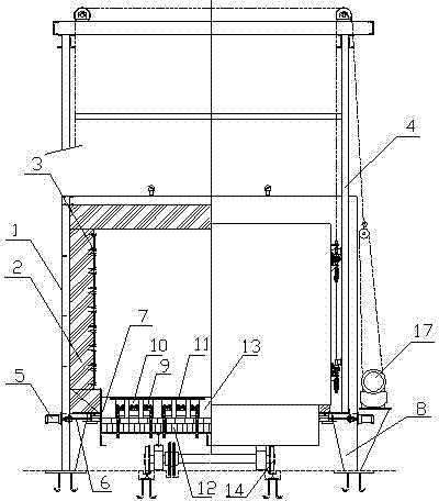
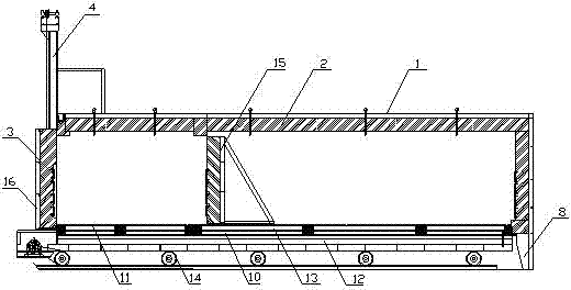
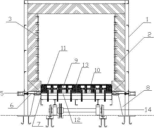
[0026] Front and rear variable-capacity trolley resistance furnace, including furnace body 1 with openings at the front and bottom, furnace lining 2, furnace door 16 and furnace door 16 lifting mechanism, electric heating element 3, trolley and trolley traveling mechanism and electrical control mechanism, It also includes a sealing mechanism and a trolley control system located at the front end of the trolley; the furnace body 1 is made into a front and rear two-section cuboid frame structure by welding section steel, and the furnace body 1 is divided into two different volumes of furnace shell skeletons , the surface of the furnace shell skeleton is welded with the furnace shell steel plate, and the furnace door adop...


PUM


Abstract

The invention discloses a front and back volume-variable trolley resistance furnace. The front and back volume-variable trolley resistance furnace mainly comprises a furnace body with openings in the front end and the bottom, a furnace lining, a furnace door, a furnace door lifting mechanism, an electric heating element, a trolley, a trolley walking mechanism, an electric appliance control mechanism, a sealing mechanism and a trolley control system at the front end of the trolley. Through structural steel welding, the furnace body is manufactured into a front furnace shell framework and a rear furnace shell framework which are different in volume; a heat insulation board is arranged in the middle of the trolley to separate the interior of the furnace body into two parts, and therefore the requirement of the different sizes for a combustion chamber is met. Two parts or devices can be heated at the same time, the production and heating cost is reduced, labor force is reduced by one half, economic benefits are improved, and the resources are fully utilized. The sealing mechanism comprises a pneumatic pushing rod, a connecting rod mechanism and a sealing pressing strip. The front and back volume-variable trolley resistance furnace is high in automation degree and good in sealing and heating effect. A furnace bottom plate, a heavy aluminum plate, a wire containing brick and a refractory brick which are sequentially and tightly arranged on the trolley from top to bottom enable heating and heat preservation effects to be perfect, and the service life of the trolley is prolonged.

Description

technical field [0001] The invention relates to heat treatment equipment, in particular to a front and rear variable-capacity trolley resistance furnace with variable volume, multiple functions, automatic sealing, good heating effect and small heat loss. Background technique [0002] The trolley type resistance furnace is a national standard energy-saving periodic operation furnace. It has an ultra-energy-saving structure and adopts a fiber structure to save electricity by up to 60%. Mainly used for high chromium, high manganese steel castings, ductile iron, rolls, steel balls, 45 steel, stainless steel and other quenching, annealing, aging and heat treatment of various mechanical parts. many. [0003] At present, trolley-type resistance furnaces mainly use one furnace to heat parts. This heating method has some problems for heating parts of different sizes. Some larger equipment and parts need a larger furnace to heat, and this single furnace It cannot meet the heating re...

Claims


Application Information

Patent Timeline
Patent Type & Authority Applications(China)
IPC IPC(8): F27B9/26F27B9/34F27B9/36F27B9/40
Inventor 傅书根沈卫东戴文卫
Owner GUANGXI SHENGLONG METALLURGICAL CO LTD
Why Eureka
Try Eureka