
Calibration method and distance measuring device based on single liquid crystal light valve phase measurement

A technology of liquid crystal light valve and phase measurement, which is applied in the direction of measuring devices, radio wave measuring systems, electromagnetic wave re-radiation, etc., can solve the problems of life interference and drift, drift of measurement distance, etc., and achieve cost reduction, lower performance requirements, The effect of improving measurement accuracy

Inactive Publication Date: 2017-08-25
JIANGSU LAITZ MEASURING& CONTROL TECH CO LTD +1
View PDF5 Cites 0 Cited by
  • Summary
  • Abstract
  • Description
  • Claims
  • Application Information

AI Technical Summary

Problems solved by technology

The system uses two independent photoelectric generating devices to generate two optical signals of the same wavelength, and because the two photoelectric generating devices, especially the laser tube, are very easy to work due to the different working time of the inner and outer optical paths and the performance difference between the two lasers. Different temperature drifts cannot be eliminated by the above principles, resulting in drifts in the measurement distance
[0016] The solutions of the above three calibration methods all have some problems such as life, interference and drift in practical applications

Method used


Image

  • Calibration method and distance measuring device based on single liquid crystal light valve phase measurement
  • Calibration method and distance measuring device based on single liquid crystal light valve phase measurement
  • Calibration method and distance measuring device based on single liquid crystal light valve phase measurement

Examples


no. 1 example

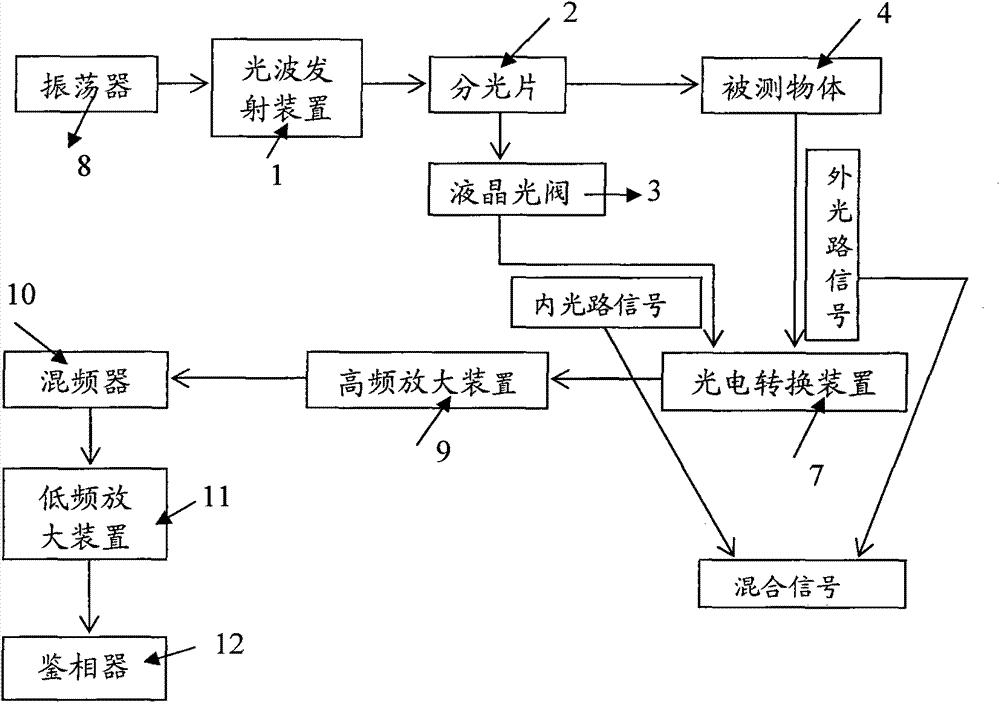
[0063] The first embodiment: as image 3 As shown, the distance measuring device of the present invention includes an oscillator 8, a transmitting device 1, a beam splitter 2, a liquid crystal light valve 3, an object to be measured 4, a photoelectric conversion device 7, and a high frequency amplification device 9, a mixer 10, and a low frequency Amplifying means 11 and phase detector 12 are used for signal conditioning and phase acquisition.

[0064] The first high-frequency oscillation signal and the second high-frequency oscillation signal with the same frequency and phase are generated by the oscillator 8, and the transmitting device 1 receives the first high-frequency oscillation signal from the oscillator, modulates the light wave, and emits it as an optical path signal; the light wave passes through The beam splitter 2 to the measured object 4 is reflected by the measured object 4 and then turned back. The photoelectric conversion device 7 receives the returned signal ...

no. 2 example

[0068] The second embodiment: as Figure 4 As shown, the distance measuring device of the present invention comprises a transmitting device 1, a beam splitter 2, a liquid crystal light valve 3, an object to be measured 4, an oscillator 8, a low frequency amplifier 11, a phase detector 12 and a receiving device 6, and the receiving device 6 is used It is used to respectively receive the external optical path signal and the mixed signal for photoelectric conversion, and perform frequency mixing with the mixed frequency signal respectively, and output the mixed signal.

[0069] In the embodiment of the present invention, the receiving device 6 can replace image 3 The photoelectric conversion device 7 and the mixer 10 in.

no. 3 example

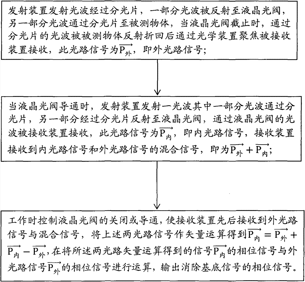
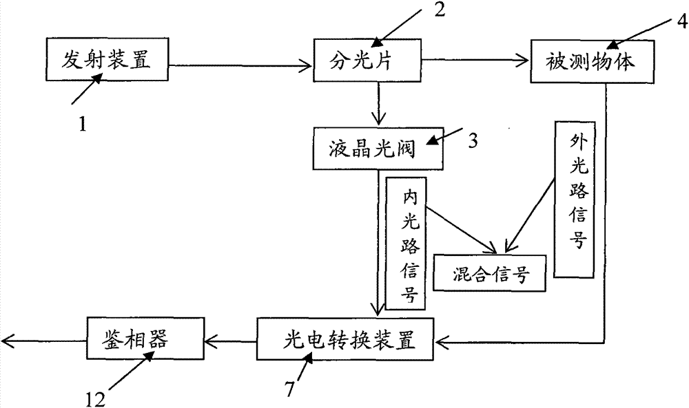
[0070] The third embodiment: as Figure 5 As shown, in the distance measuring device of the present invention, the phase-locked loop 13 and the driving circuit 14 drive the transmitting device 1 to emit light waves according to the high-frequency oscillation signal, and a part of the light waves passes through the light splitter 2, while the other part is reflected by the light wave splitter 2 to the liquid crystal Light valve 3; when the liquid crystal light valve 3 is cut off, the receiving device 6 only receives the external light path signal reflected by the measured object 4 after passing through the spectroscopic sheet 2 to the measured object 4; when the liquid crystal light valve 3 is turned on, The light waves emitted by the transmitting device 1 are reflected by the beam splitter 2 and pass through the liquid crystal light valve 3 as the internal light path signal. At this time, the receiving device 6 simultaneously receives the mixed signal of the external light path...


PUM


Abstract

The invention discloses a calibration method and range finding apparatus based on single liquid crystal light valve phase measuring. The apparatus comprises an emitting device and a light splitting sheet which are successively arranged. The light splitting sheet is successively provided with a liquid crystal light valve and a receiving device in a reflection axial direction, a receiving lens is arranged in front of the receiving device, and the emitting device and the receiving device are respectively connected with a circuit board; the emitting device emits light waves to the light splitting sheet, and when the liquid crystal light valve is cut off, the receiving device receives an outer optical path signal reflected by a tested object through the light splitting sheet; and when the liquid crystal light valve is conducted, the receiving device receives a mixed signal of the outer optical path signal reflected by the tested object through the light splitting sheet and an inner optical signal which is reflected by the light splitting sheet and passes through the liquid crystal light valve. Through vector operation of the two signals, the inner optical signal of the outer optical signal which has a common mode eliminated is obtained, and then a phase signal which has a substrate signal eliminated is calculated through the inner optical path signal and the outer optical path signal. The method and apparatus provided by the invention have the advantages of long life, short response time, high precision, low cost and prevention of same-frequency interference.

Description

technical field [0001] The invention relates to the field of photoelectric ranging, in particular to a calibration method based on phase measurement of a single liquid crystal light valve and a ranging device thereof. Background technique [0002] Laser is a new technology developed in the 1960s. It is a kind of light with pure color, highly concentrated energy and good directionality. The laser technology developed from this has solved many technical obstacles that cannot be solved by traditional technology. Laser range finder is an instrument that uses laser to measure distance. It has been paid more and more attention by civil, military and industrial industries in the fields of length, height, distance, speed and shape. It has been widely used in the following fields abroad: Major industrial and mining enterprises, power petrochemical, water conservancy, communication, environment, construction, geology, police, fire protection, blasting, navigation, railway, anti-terro...

Claims


Application Information

Patent Timeline
Patent Type & Authority Patents(China)
IPC IPC(8): G01S17/08G01S7/497
CPCG01S7/497G01S17/08
Inventor 杜鑫乔佰文查晓怡
Owner JIANGSU LAITZ MEASURING& CONTROL TECH CO LTD
Learn More