
Automatic discharge mechanism for coiler for trimmings

An automatic unloading and edge rolling technology, applied in the field of waste edge coiling machine, can solve the problems of increasing operating time and energy of operators, damage to waste edge rolling equipment, etc., to reduce unloading time, reduce workload, and avoid scratching The effect of wounding and smashing

Active Publication Date: 2015-04-22
广州市力鼎汽车零部件有限公司
View PDF7 Cites 1 Cited by
  • Summary
  • Abstract
  • Description
  • Claims
  • Application Information

AI Technical Summary

Problems solved by technology

Although the waste edge coiler with this structure is simple in structure and easy to unwind, under the action of the jumping roller, the recovered waste edge is more likely to cover the entire recycling section, but when unloading, the waste edge after unwinding The roll is still squeezed in the guide baffles on both sides and must be manually assisted to complete the unloading
It increases the operating time and energy of the operator, and there is a very serious safety hazard. At the same time, the direct fall of the waste edge roll is also easy to cause damage to the equipment.

Method used


Image

  • Automatic discharge mechanism for coiler for trimmings
  • Automatic discharge mechanism for coiler for trimmings
  • Automatic discharge mechanism for coiler for trimmings

Examples


Embodiment Construction

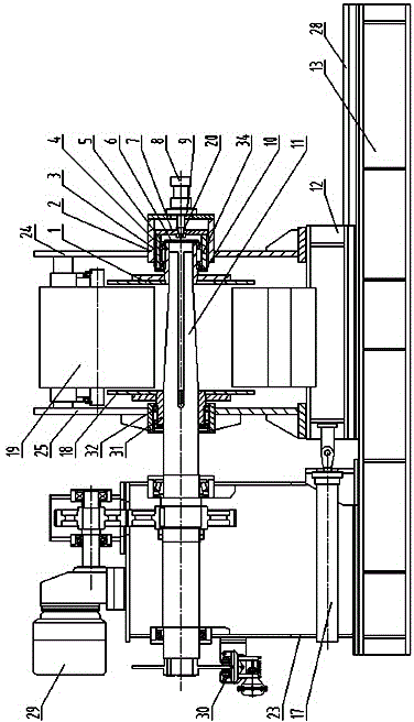
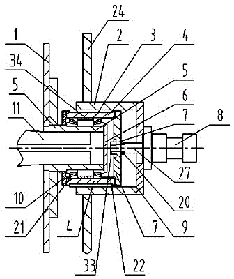
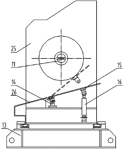
[0015] like figure 1 , figure 2 The shown automatic unloading mechanism of a waste edge coiler includes a base 13, on which a fixed seat 23 and a movable seat 12 are arranged, and the base 13 is provided with a slide rail 28 extending forward and backward in a guiding direction, and the movable The seat 12 is slidingly assembled on the slide rail 28, and the unwinding oil cylinder 17 hinged with the two is provided between the movable seat 12 and the fixed seat 23, and the rotation of the axial limit on the fixed seat 23 is equipped with a rotary shaft 11, and the rotary shaft 11 The axis of rotation of the rotary shaft extends along the front and rear directions. The front end of the rotary shaft 11 is provided with a recovery section for reclaiming corresponding waste edges. The rotary shaft 11 is connected with the drive motor 29 through a transmission mechanism.

[0016] The movable seat 12 is provided with a front vertical plate 24 and a rear vertical plate 25 arranged ...


PUM


Abstract

An automatic discharge mechanism for a coiler for trimmings comprises a fixed base and a movable base. A front vertical plate and a rear vertical plate are arranged on the movable base side by side in a spaced mode in the front-back direction. An axial through hole through which a recycling working section of a rotating shaft is allowed to penetrate is formed in the middle of the rear vertical plate. The recycling working section of the rotating shaft is assembled on the rear vertical plate and the front vertical plate in an axial-sliding and rotating mode. A fixed blocking disc is fixedly arranged on a rear sleeve. A memorial arch sleeve is fixedly arranged in a central through hole in the middle of the front vertical plate. A guiding key groove is formed in the inner wall of the memorial arch sleeve. An outer flange is fixed to the front end of the memorial arch sleeve. An extruding oil cylinder is fixedly arranged on the outer flange. A piston rod of the extruding oil cylinder penetrates through a central through hole in the outer flange to be fixedly connected with an inner flange. The outer edge of the middle sleeve is provided with guiding keys matched with the guiding key groove. The middle sleeve is inserted into the memorial arch sleeve in an axial sliding-fit mode. The front portion of the front sleeve is inserted into a self-aligning roller bearing inner race in the middle sleeve. The front end of the rotating shaft is inserted into the front sleeve, and a movable blocking disc is fixedly arranged at the rear end of the front sleeve.

Description

technical field [0001] The proposal relates to a waste edge coiler, in particular to a mechanism for realizing the automatic unloading of the waste edge coiler. Background technique [0002] In the cold rolling production line, in order to meet the width requirements of the finished strip, and at the same time, its edges on both sides are irregular and have microscopic corrugations and other defects, which make the stress distribution on the entire strip surface uneven and affect its overall quality. Disc shears are required. The unqualified edges on both sides of the strip are cut off, and the cut waste edges are recovered by the corresponding waste edge coiler. [0003] Existing scrap coilers such as the "cold-rolled strip scrap coiler" disclosed in Chinese patent CN 102615104 A, this scrap coiler includes a frame and a recovery shaft, and the recovery shaft is provided with a In the recycling section, above the recycling section, there is a baffle plate that extends ...

Claims


Application Information

Patent Timeline
IPC IPC(8): B21C47/24
Inventor 张世翰徐济声刘玉章张明李剑峰吴林荀继平
Owner 广州市力鼎汽车零部件有限公司
Learn More