Press type automatic tin supply electric soldering iron

An electric soldering iron, automatic technology, applied in the electronic field, can solve the problems of low welding operation efficiency, inconvenient welding operation, long time consumption, etc., achieve the effect of automatic supply and control of welding flow, simple and convenient operation, and improve welding efficiency

Inactive Publication Date: 2015-04-22
HUBEI UNIV OF TECH
View PDF10 Cites 20 Cited by
  • Summary
  • Abstract
  • Description
  • Claims
  • Application Information

AI Technical Summary

Problems solved by technology

For example, the patent with the publication number of CN 101837496 A and the patent with the publication number of CN2062266 both disclose an electric soldering iron for automatic tin supply. The problem of inconvenience, but this kind of electric soldering iron has a complex structure and high cost, is not practical and is not easy to maintain; the patent with the authorized announcement number of CN201220313Y discloses an automatic tin supply electric soldering iron, which mainly consists of a soldering iron tip, a heating resistance wire, and a soldering iron Body, tin supply device, rear cover, and return spring, which can realize the soldering operation with one hand, but the device cannot realize real-time tin supply. Specifically, when the temperature of the electric soldering iron reaches the working temperature, manual operation is required. Press down the upper button of the tin supply device, so that the solder particles enter the front cavity through the front tin outlet, and the solder particles entering the cavity can be heated and melted by the heating device and flow to the solder point
Therefore, it takes a long time for this electric soldering iron to realize a soldering process, and because the amount of solder particles heated each time entering the front cavity is limited, in the soldering process with a large demand for soldering tin, not only it is necessary to manually control the tin supply device continuously The upper button, and the time for waiting for the solder particles to melt also increases cumulatively. The welding operation efficiency is low, not energy-saving, and the ideal welding effect cannot be achieved at the same time. It is not suitable for soldering process operations that require a large amount of tin at a time.

Method used


Image

  • Press type automatic tin supply electric soldering iron
  • Press type automatic tin supply electric soldering iron
  • Press type automatic tin supply electric soldering iron

Examples


Embodiment 1

[0024] Below in conjunction with accompanying drawing technical scheme of the present invention is described further as follows:

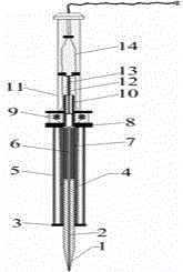
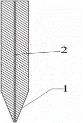
[0025] Such as figure 1As shown, a touch-pressure automatic tin supply soldering iron includes a soldering iron head (1), a heating device (5), a tin melting device (7), a pressure piston (10) and a handle device (11), and the soldering iron The head (1), the tin melting device (7) and the pressure piston (10) are combined together. The inner cavity of the three is connected and does not contact with the outside air, forming a closed inner cavity. Under certain circumstances, it can ensure that the liquid tin in the tin cavity does not fall. The soldering iron tip (1) has a tin-holding cavity (2) inside, the tin-holding cavity (2) is designed with a diameter of 0.5 mm, and is mainly used to accommodate solder liquid, and the tip of the soldering iron tip (1) has a tin-holding cavity The cavity (2) has the same pores through which solder liq...

Embodiment 2

[0032] For a better understanding of the present invention, the method of using the electric soldering iron of the present invention will be further described below in conjunction with the examples:

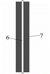
[0033] During specific use, when the power is plugged in, the two copper sheets (9) drawn out by the wires at the bottom of the handle device (11) are heated, and then transfer the heat to the two copper sheets (9) led out by the inner wires of the heating device (5). ), heating the heat transfer cylinder (4) wound with resistance wire through the wire (14) to transfer heat to the soldering iron tip (1) and the tin melting device (7), and melt the solder inside the tin melting cavity (6) from solid to liquid , and at the same time make the temperature of the soldering iron tip (1) reach the working temperature. Then gently touch the tip of the soldering iron tip (this process is completed within about 2-3 seconds), thereby pushing the combination of the soldering iron tip (1), th...


PUM

PropertyMeasurementUnit
diameteraaaaaaaaaa
diameteraaaaaaaaaa

Abstract

The invention relates to a press type automatic tin supply electric soldering iron which comprises a soldering iron head, a heating device, a tin melting device, a pressure piston and a handle device. The soldering iron head, the tin melting device and the pressure piston are combined together. Inner cavities of the soldering iron head, the tin melting device and the pressure piston are communicated and do not make contact with external air to form a closed inner cavity body. The heating device is mainly used for heating the soldering iron head and melting solid soldering tin in the tin melting cavity into molten tin. The tin melting cavity is mainly used for melting solid soldering tin. A inflator principle is adopted for the pressure piston, the internal pressure intensity can be changed by pushing a pressure rod, and therefore air flow is produced, and air is exhausted from an air outlet; the pressure rod is sleeved with a spring device which is used for making the electric soldering iron rapidly rotate back in a non-press state. The press type automatic tin supply electric soldering iron can be operated by one hand to control the amount of soldering tin, and can conduct automatic supply in real time and control the welding flow, effectively improve the welding efficiency in an electronic industry and save cost.

Description

technical field [0001] The invention relates to the field of electronic technology, in particular to an electric soldering iron, in particular to a touch-pressure automatic tin-supply electric soldering iron. Background technique [0002] Soldering iron is one of the necessary tools in the electronics industry. It is mainly used for welding components and wires. According to the mechanical structure, it can be divided into internal heating type electric soldering iron and external heating type electric soldering iron. During the use of the electric soldering iron, by energizing and heating the heating device, the heat is transferred to the soldering iron tip to reach a temperature higher than the melting point of the solder, and then the solder wire is used as the welding material, and the tin wire is melted by the heated soldering iron tip close to the soldering iron tip. In liquid state, drop it on the soldering point, and the soldering will be completed after the liquid s...

Claims


Application Information

Patent Timeline
Patent Type & Authority Applications(China)
IPC IPC(8): B23K3/03B23K3/06
CPCB23K3/04B23K3/0607
Inventor 黄文聪常雨芳张威亚李舟孙磊武明虎徐操宋阿妮肖义平王粟
Owner HUBEI UNIV OF TECH
Why Eureka
Try Eureka