
High-accuracy powerful hydraulic machine

A hydraulic press, powerful technology, applied in punching presses, presses, fluid pressure actuating devices, etc., can solve the problems of heavy volume, inconvenient transportation and use, large shape of hydraulic cylinders, etc., to achieve small size, convenient production layout, human body low impact effect

Inactive Publication Date: 2015-04-22
佛山市骤威液压机械制造有限公司
View PDF6 Cites 0 Cited by
  • Summary
  • Abstract
  • Description
  • Claims
  • Application Information

AI Technical Summary

Problems solved by technology

[0003] At present, the conventionally used presses above 70MPa, due to the strong pressure generated, make the hydraulic cylinder large in shape and heavy in volume, so the liquid volume provided by the liquid supply station is required to be large, making the relationship between the hydraulic cylinder and the liquid supply station and the control cabinet The rooms are independent of each other and connected by pipelines, which is extremely inconvenient to transport and use, especially in the upstairs factory

Method used


Image

  • High-accuracy powerful hydraulic machine
  • High-accuracy powerful hydraulic machine
  • High-accuracy powerful hydraulic machine

Examples


Embodiment 1

[0039] Example 1

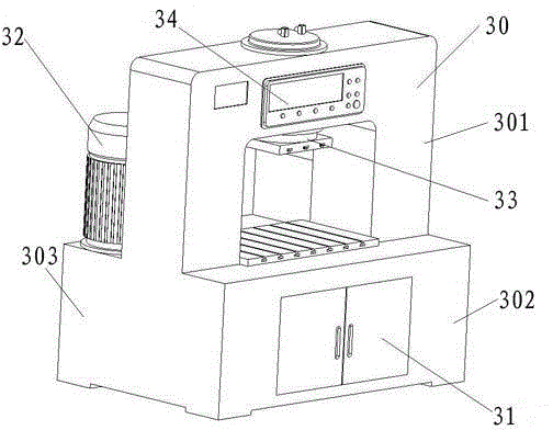
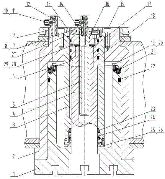
[0040] Such as figure 1 with figure 2 As shown, the high-precision powerful hydraulic press of the present invention includes a frame body 30, the middle part of which is a working area, and a hydraulic cylinder 33 is arranged above the working area, wherein the rear portion of the frame body 30 is set as A hydraulic station 32 , the hydraulic station 32 communicates with the hydraulic cylinder 33 to supply liquid; the front part of the frame body 30 is provided with an electric control cabinet 31 , and the electric control cabinet 31 is connected to and controls the hydraulic station 32 . The hydraulic cylinder 33 is located above the middle of the working area, and an electric control board 34 is arranged above the working area, and the electric control board 34 is connected to the electric control cabinet 31 . The high-precision powerful hydraulic machine can be a monolithic structure or a combination of split structures, so the front part of the fra...

Embodiment 2

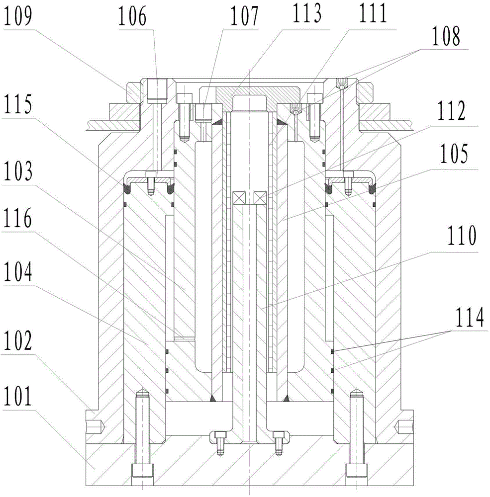
[0045] Such as image 3 with Figure 4 As mentioned above, this embodiment is similar to Embodiment 1, except that the hydraulic cylinder 33 adopts a different structure. In the high-precision and powerful hydraulic machine of the present invention, the hydraulic cylinder 33 includes a master cylinder block 102, so The inner top of the master cylinder body 102 is sealingly connected with a return cylinder body 103, and a cylindrical main plunger 104 is sleeved between the inner wall of the master cylinder body 102 and the outer wall of the return cylinder body 103, and the top of the main cylinder body 104 is The inner and outer walls are respectively provided with dynamic seals, that is, the top outer wall of the main plunger 104 and the top inner wall of the main plunger 104 are respectively provided with L-shaped sealing rings 105, so that the main plunger 104 and the master cylinder A dynamic seal is formed between the body 102 and the return cylinder body 103 respectivel...


PUM


Abstract

The invention discloses a high-accuracy powerful hydraulic machine and belongs to the technical field of hydraulic devices. The high-accuracy powerful hydraulic machine comprises a rack body, the middle of the rack body is a working area, a hydraulic cylinder is arranged above the working area, a hydraulic station is disposed in rear of the rack body, the hydraulic station is communicated with the hydraulic cylinder to provide liquids, an electronic control cabinet is arranged in front of the rack body, and the electronic control cabinet is connected with the hydraulic station to control the hydraulic station. The high-accuracy powerful hydraulic machine has the advantages that the structure is simple, operation is simple and convenient, conveying and usage are convenient and rapid, the hydraulic cylinder, a liquid supply station and the control cabinet are integrated so that the machine is compact in structure, small in size and floor space and applied to factories located upstairs, and production arrangement of an assembly line is convenient.

Description

[0001] The patent application of the present invention is a divisional application of the invention patent with the application number 201310333431.5, the application date is 2013-08-02, and the invention name is high-precision powerful hydraulic press. technical field [0002] The invention relates to a hydraulic device, in particular to a pocket hydraulic device. Background technique [0003] At present, the conventionally used presses above 70MPa, due to the strong pressure generated, make the hydraulic cylinder large in shape and heavy in volume, so the liquid volume provided by the liquid supply station is required to be large, making the relationship between the hydraulic cylinder and the liquid supply station and the control cabinet The rooms are independent of each other and connected by pipelines, which is extremely inconvenient to transport and use, especially in the upstairs factories. Contents of the invention [0004] The purpose of the present invention is to...

Claims


Application Information

Patent Timeline
Patent Type & Authority Applications(China)
IPC IPC(8): B30B1/36B30B15/04B30B15/00F15B15/20
CPCB30B1/36B30B15/00B30B15/04F15B15/20
Inventor 劳光汉
Owner 佛山市骤威液压机械制造有限公司
Learn More