Spreader

A technology of spreading machine and cloth guide, applied in the field of spreading machine, can solve the problems of high labor intensity of workers and waste of labor resources, etc.

CN104528454BInactive Publication Date: 2016-09-07常熟市龙略机电有限公司
10 Cites 4 Cited by

Patent Information

Authority / Receiving Office
CN · China
Patent Type
Patents(China)
Current Assignee / Owner
Publication Date
2016-09-07
Estimated Expiration
Not applicable · inactive patent

Smart Images

  • Figure 1
    Figure 1
  • Figure 2
    Figure 2
  • Figure 3
    Figure 3
Patent Text Reader

Abstract

The invention relates to a fabric spreading machine and belongs to the technical field of textile printing and dyeing machinery. The fabric spreading machine comprises a machine frame, a fabric guide mechanism, a fabric spreading mechanism, an untwisting device, an automatic deflection detection and correction device and a guide-out roller. The fabric spreading machine is characterized in that the untwisting device comprises an untwisting frame base, an untwisting frame, a detection roller, an untwisting fabric guide wheel, a rotary cylinder bearing block, a rotary cylinder, a rotary disk, a pair of untwisting transition wheels and an untwisting servo motor, the untwisting frame base is composed of a first ladder, a second ladder and a platform, one side of a left wallboard of the untwisting frame is provided with a first signal collector, one side of a right wallboard of the untwisting frame is provided with a second signal collector, a first signal trigger coil is fixed to the left end of the detection roller, and a second signal trigger coil is fixed to the right end of the detection roller; the fabric spreading mechanism comprises a first fabric stretching roller, a second fabric stretching roller, a tension roller, a fabric stretching roller driving device, a tension roller driving device and a pair of tension roller manual adjustment devices. The structure is simplified, the response speed of the first signal collector and the response speed of the second signal collector are increased, and reliability of the first signal collector and the second signal collector is improved; deflected fabric is corrected automatically, and strength is relieved; selvages will not curl.
Need to check novelty before this filing date? Find Prior Art

Description

technical field

[0001] The invention belongs to the technical field of textile printing and dyeing machinery, and in particular relates to a spreading machine. Background technique

[0002] The aforementioned spreading machine is also called an open-width machine, a stretching machine or a stretcher, and the like. As known in the industry, the fabric obtained from the previous weaving process needs to be processed in subsequent processes, such as wet finishing (such as silicone soft finishing) process, after wet finishing, the fabric needs to be dehydrated by calendering or centrifugal dehydration. Because the shape of the fabric changes to a certain twist in the wet finishing and dehydration process, figuratively speaking, the shape of the fabric is like the state of fried dough sticks in daily food. If it is not untwisted, it cannot enter the subsequent process such as drying. Drying, falling cloth, winding process.

[0003] The untwisting device and the centering device...

Examples

Embodiment Construction

[0024] In order to enable the examiners of the patent office, especially the public, to understand the technical essence and beneficial effects of the present invention more clearly, the applicant will describe in detail the following in the form of examples, but none of the descriptions to the examples is an explanation of the solutions of the present invention. Any equivalent transformation made according to the concept of the present invention which is merely formal but not substantive shall be regarded as the scope of the technical solution of the present invention.

[0025] In the following descriptions, all concepts related to the directionality or azimuth of up, down, left, right, front and rear are aimed at the position state of the figure being described, and therefore cannot be understood as a special limitation to the present invention .

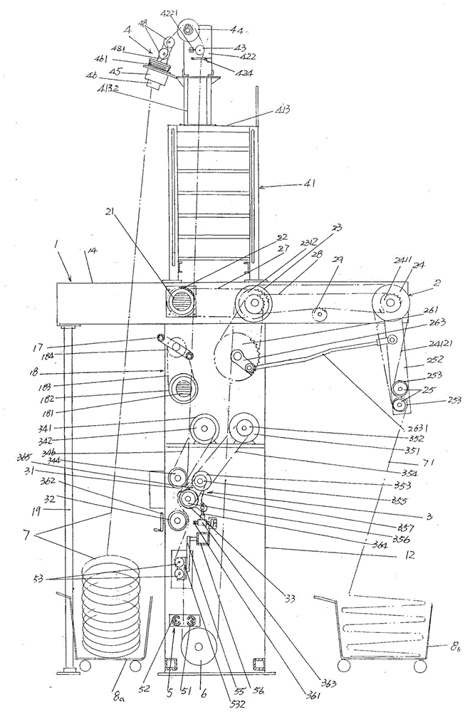
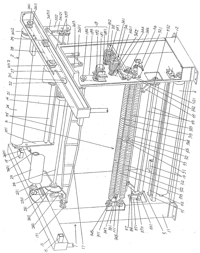
[0026] See figure 1 , in the figure 1 The frame 1 is given in ; the cloth guide mechanism 2 arranged on the frame 1 correspond...