Coated insulating material for overall insulation of railway switch installation device

An installation device and integral insulation technology, which is applied in the field of wrapped insulating materials, can solve the problems of permanent deformation bolts, gaps between the cladding and steel parts, and the inability to achieve the insulation effect, and achieve the effect of improving the insulation level.

Inactive Publication Date: 2015-04-22
成都瑞吉龙科技有限责任公司 +1
View PDF7 Cites 8 Cited by
  • Summary
  • Abstract
  • Description
  • Claims
  • Application Information

AI Technical Summary

Problems solved by technology

[0010] However, in the implementation process, the existing wrapping materials are generally BMC, epoxy or phenolic glass fiber materials. Traditional materials will cause permanent deformation after fastening and the bolts will loosen after a period of use; and at low temperature When the hardness increases, the more brittle the material, it may cause the insulation material to break when it is fastened, so that the insulation effect cannot be achieved.
In addition, from the perspective of thermal expansion and contraction, no two substances have the same thermal expansion and contraction properties. Generally, the parts that adopt the cladding process are steel parts, and the thermal expansion and cold contraction stress of steel parts is quite large. If The steel parts are clad with traditional phenolic glass fiber insulation materials or hard insulation materials. At low temperatures, due to the different shrinkage ratios (or shrinkage rates) of the two materials, it is likely to be caused by this difference. It will cause a gap between the cladding body and the steel part, resulting in peeling of the bond; under high temperature conditions, due to thermal expansion of the steel part, if the outer cladding material is made of the original phenolic glass fiber insulating material or hard insulating material, Cladding is prone to cracking

Method used


Image

  • Coated insulating material for overall insulation of railway switch installation device
  • Coated insulating material for overall insulation of railway switch installation device
  • Coated insulating material for overall insulation of railway switch installation device

Examples


Embodiment 1

[0058] Component A: DMTDA, M-DEA mixture 15 parts

[0059] Component B: 100 parts of prepolymer made of MDI and PTMEG with NCO%=9%.

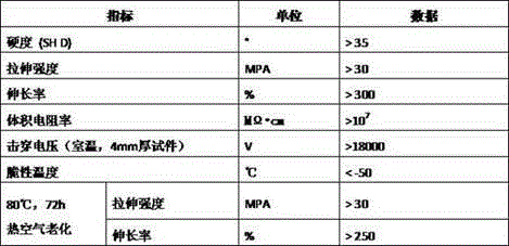
[0060] The insulating material made by mixing components A and B can achieve the following properties.

[0061]

Embodiment 2

[0063] A component: MOCA, DMTEA mixture 18 parts

[0064] Component B: 100 parts of prepolymer with NCO%=10% made of MDI, TDI, PTMEG and polyoxypropylene polyol.

[0065] The insulating material made by mixing components A and B can achieve the following properties.

[0066]

Embodiment 3

[0068] A component: MOCA, M-MIPA mixture 16 parts

[0069] Component B: 100 parts of prepolymer made of MDI, TDI and polyoxypropylene polyol with NCO%=7%.

[0070] The insulating material made by mixing components A and B can achieve the following properties.

[0071]


PUM

PropertyMeasurementUnit
thicknessaaaaaaaaaa
electrical resistivityaaaaaaaaaa
electrical resistanceaaaaaaaaaa

Abstract

The invention provides a coated insulating material for overall insulation of a railway switch installation device. The coated insulating material for overall insulation of railway switch installation device refers to an environment-friendly high polymer resin insulating material. The insulating material is prepared by the following steps: preparing a component A from a mixture of a hydroxyl-terminated polymer or an amino-terminated polymer containing activated hydrogen, low-molecular-weight polyhydric alcohols, polyamine, poly-hydroxy acids or other chain extenders and other weather-resistant protective materials; taking diisocyanate and polyisocyanates monomers, polymers, derivatives, or a prepolymer or a semi-prepolymer prepared by the reaction between a hydroxyl-terminated compound or an amino-terminated compound with isocyanate as a component B, and adding various protective materials according to the construction environment to prepare the double-component special insulating material for the railway switch with the solid content of 100 percent, thereby obtaining the insulating material disclosed by the invention.

Description

technical field [0001] The invention relates to a manufacturing method of a wrap-type insulating material used for the overall insulation of a railway turnout installation device, as well as the field and method of use of the insulating material. Background technique [0002] Turnout is the key equipment for normal railway transportation. With the increase of railway transportation speed and the shortening of driving intervals, the requirements for the turnout system are getting higher and higher. At the same time, the insulation requirements for turnouts and related equipment are also getting higher and higher. The importance of safety protection The reliability has also become increasingly prominent. In recent years, new requirements such as safer and maintenance-free insulation have been put forward for the insulation of turnouts and related equipment. [0003] Nylon 1010 is generally used for the insulation of railway turnout installation devices (including turnout squar...

Claims


Application Information

Patent Timeline
Patent Type & Authority Applications(China)
IPC IPC(8): C08G18/76C08G18/66C08G18/48C08G18/32C08G18/10C08G18/12C08L75/08
CPCC08G18/7671C08G18/10C08G18/12C08G18/324C08G18/3243C08G18/4804C08G18/4854C08G18/6685C08G18/7607C08G18/7621
Inventor 王平胡吉
Owner 成都瑞吉龙科技有限责任公司
Why Eureka
Try Eureka