Transformer with built-in cabin used for wind power generation

A transformer, built-in technology, applied in transformer/inductor casing, transformer/inductor cooling, transformer/inductor magnetic core, etc., can solve the problem of poor sealing performance of transformers, easy pollution of the environment, poor coordination and reliability, and increased line loss and other problems, to achieve the effect of convenient and reliable connection, safe operation and stable electrical performance

Inactive Publication Date: 2010-06-16
沈阳幸森电气设备有限公司
View PDF0 Cites 3 Cited by
  • Summary
  • Abstract
  • Description
  • Claims
  • Application Information

AI Technical Summary

Problems solved by technology

[0005] The purpose of the present invention is to overcome the above-mentioned deficiencies in the prior art, aiming at the defects of the existing wind power substation adopting the external installation method that is separated from the engine room and the tower: the cost is increased due to civil works and other projects, and the connecting cables are long. Causes increased line loss, poor coordination and control reliability of long-distance operation, poor sealing performance of transformers, easy to pollute the environment, loose structure and large footprint, etc., providing a compact structure, suitable for built-in installation of wind turbine nacelles, Light weight, small footprint, saving investment, low operating cost, convenient maintenance, and excellent environmental protection performance in the nacelle built-in transformer for wind power generation (the high voltage and low voltage units of the substation are omitted)

Method used


Image

  • Transformer with built-in cabin used for wind power generation
  • Transformer with built-in cabin used for wind power generation
  • Transformer with built-in cabin used for wind power generation

Examples


Embodiment Construction

[0029] The concrete technical scheme of the present invention will be further described below in conjunction with embodiment:

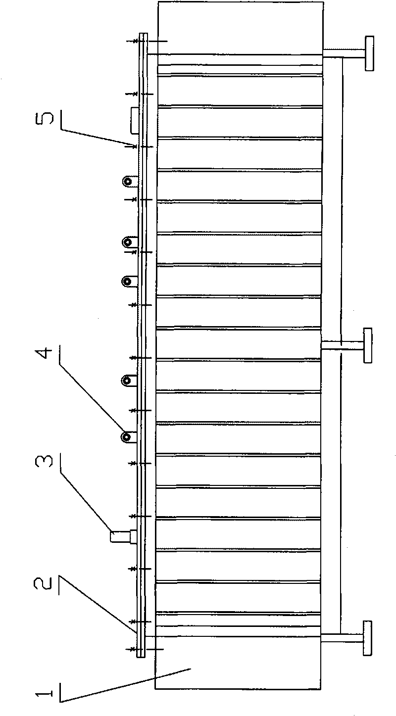
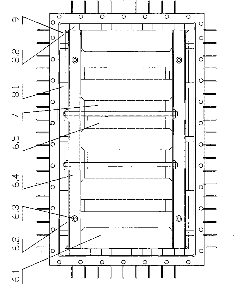
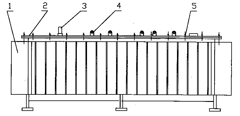
[0030] Such as Figure 1 ~ Figure 2 As shown, the built-in transformer for wind power generation includes a corrugated oil tank 1, an iron core, a three-phase winding 7, an external lead joint 4 and an insulation system, wherein

[0031] Corrugated oil tank 1: the bottom is made of thicker steel plate bent into a groove shape and welded; the upper part is cut and welded with angle steel to form a square frame, and the surrounding is made of thicker steel plate bent and welded into strips of angular cross-section, and the three are combined into four sides A box with an opening, a lower groove, and an upper opening; corrugated sheets are welded on the four sides where there are openings. After all welding is completed, a pressure leak test is carried out, and the qualified transfer to the painting process.

[0032] Tank cover 2: It is made of thicker ...


PUM


Abstract

The invention provides a transformer with a built-in cabin used for wind power generation, comprising an oil tank, an iron core, a three phase winding, an externally-introduced joint and an insulating system. The transformer with a built-in cabin used for wind power generation is characterized in that the transformer body is of a horizontal type; the iron core is a three-phase five-column iron core structure which is arranged in a horizontal type; the inner layer of the three phase winding is a low-voltage cylindrical winding which is used for paving oil passage stays after winding is completed, and then the high-voltage winding is wound simultaneously; the case of the oil tank is a frame which is formed by bent thick steel plates; the case of the oil tank is externally welded with rippleplates, is sealed by adhesive tapes together with the case cover; the externally-introduced joint is an elbow-type cable terminal plug-in connector; and the insulating system is a solid-liquid mixinginsulating system. The invention changes the structure of the current wind power generation transformer to meet the use requirement of the built-in cabin for wind power generation; and the invention is characterized by full insulation, full sealing, stable electric property, good mechanical performance, good weather resistance, convenient and reliable connection, dampproof and dustproof properties.

Description

technical field [0001] The invention relates to a transformer, in particular to a transformer built in a nacelle for wind power generation, and belongs to the technical field of wind power equipment. Background technique [0002] Wind energy is a renewable, green and environment-friendly energy source. In the context of global energy shortage and increasingly serious environmental pollution, wind power generation is effectively developed and utilized. Its development prospects are considerable both in terms of economic and social benefits. With the development of wind power generation technology in China, the generating capacity of a single unit is increasing. Within the effective wind field area, the larger the generating capacity of a single unit, the higher the efficiency and the higher the output energy per square meter. Due to the increase in the capacity of a single machine, the mode of power generation and transformation will inevitably change, so it is imperative to ...

Claims


Application Information

Patent Timeline
Patent Type & Authority Applications(China)
IPC IPC(8): H01F27/26H01F27/24H01F27/28H01F27/02H01F27/32H01F27/14
Inventor 贝晓东
Owner 沈阳幸森电气设备有限公司
Why Eureka
Try Eureka