Double-clutch speed changing box and clutch hydraulic control system thereof

A hydraulic control system, dual clutch technology, applied in transmission control, toothed components, belts/chains/gears, etc., can solve the problem of insufficient cooling lubricating oil, engine power cannot be transmitted, clutch temperature rise, etc. problems, to avoid failure or burnout, to achieve timely cooling, and to solve the effect of power interruption

Active Publication Date: 2015-04-22
ANHUI JIANGHUAI AUTOMOBILE GRP CORP LTD
View PDF5 Cites 9 Cited by
  • Summary
  • Abstract
  • Description
  • Claims
  • Application Information

AI Technical Summary

Problems solved by technology

[0003] In the working conditions of high-speed driving, frequent start-up, or high-acceleration start-up, the friction clutch will generate a lot of heat, and the existing dual-clutch hydraulic control system only has one clutch lubrication channel, which cannot provide enough cooling lubricating oil fluid, the heat generated by the dual clutch cannot be taken away in time, which will inevitably lead to an increase in the temperature of the clutch. After the clutch temperature exceeds its allowable operating temperature (for example, 130 degrees), in one case, the clutch enters the protection state and the dual clutch disengages. The power of the engine cannot be transmitted to the wheels, causing the vehicle to lose power during driving; in another case, when the temperature rises above a certain temperature, the dual clutch will be directly burned

Method used


Image

  • Double-clutch speed changing box and clutch hydraulic control system thereof
  • Double-clutch speed changing box and clutch hydraulic control system thereof
  • Double-clutch speed changing box and clutch hydraulic control system thereof

Examples


Embodiment Construction

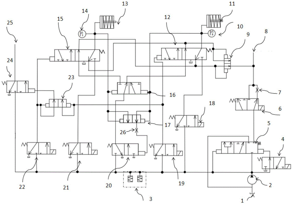
[0028] The core of the present invention is to provide a clutch hydraulic control system for a dual-clutch gearbox, which can realize timely cooling of the clutch, improve cooling efficiency, and avoid failure or burning of the clutch under special working conditions. Another core of the present invention is to provide a dual-clutch gearbox including the above clutch hydraulic control system.

[0029] In order to enable those skilled in the art to better understand the technical solutions of the present invention, the present invention will be further described in detail below in conjunction with the accompanying drawings.

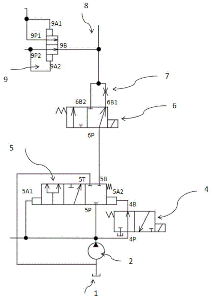
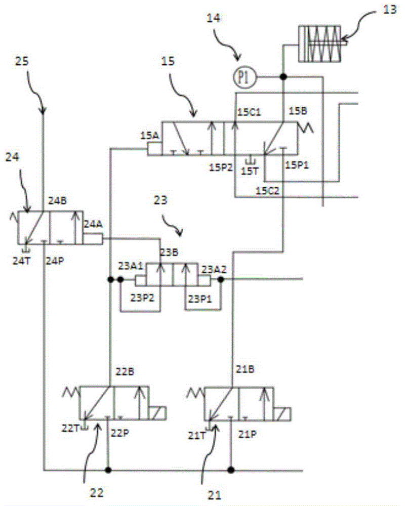
[0030] Please refer to Figure 1 to Figure 4 , figure 1 It is a structural schematic diagram of a specific embodiment of the clutch hydraulic control system provided by the present invention; figure 2 for figure 1 The enlarged view of the second cooling control oil circuit in the shown clutch hydraulic control system; image 3 for figure 1 The enlarg...


PUM


Abstract

The invention discloses a clutch hydraulic control system and a double-clutch speed changing box thereof. The double-clutch speed changing box comprises a first cooling control oil path and a second cooling control oil path, wherein the second cooling control oil path and a first double-clutch control oil path are connected in parallel. The second cooling control oil path comprises a clutch cooling electromagnetic valve, an oil supply port of the clutch cooling electromagnetic valve is communicated with an oil tank, an oil outlet of the clutch cooling electromagnetic valve is communicated with a clutch cooling oil path through a throttling valve at a first communication position, and the oil outlet of the clutch cooling electromagnetic valve is communicated with the clutch cooling oil path at a second communication position. According to the clutch hydraulic control system, two sources are arranged for cooling lubrication of clutches, another path of cooling channel is formed by additionally arranging the clutch cooling electromagnetic valve on the basis that only a cooling slide valve is used traditionally, so that the lubrication of the clutches is ensured to the maximum degree, the clutches are cooled in time, and the problem of power interruption caused by the excessively high temperature of the clutches is solved.

Description

technical field [0001] The invention relates to the technical field of hybrid vehicle engineering, in particular to a clutch hydraulic control system for a dual-clutch gearbox. The present invention also relates to a dual-clutch gearbox comprising the above clutch hydraulic control system. Background technique [0002] Dual-clutch gearboxes are increasingly widely used in the automobile manufacturing industry. A typical dual-clutch gearbox includes two coaxial nested or parallel arranged clutches, coaxial, two input shafts arranged in an inner and outer nested arrangement, two parallel arranged The output shaft of the output shaft, a plurality of synchronizer devices arranged on the output shaft, a plurality of shift forks and differentials, etc. As the core component of the dual-clutch gearbox, the clutch works through the control of the hydraulic system. [0003] In the working conditions of high-speed driving, frequent start-up, or high-acceleration start-up, the fricti...

Claims


Application Information

Patent Timeline
Patent Type & Authority Applications(China)
IPC IPC(8): F16H61/40F16H63/34
CPCF16H61/40F16H61/4157F16H61/4165F16H63/34
Inventor 王中华王英翁晓明杨士先闫亚潘
Owner ANHUI JIANGHUAI AUTOMOBILE GRP CORP LTD
Why Eureka
Try Eureka