Displacement amplifying type 2D electro-hydraulic proportional directional valve

An electro-hydraulic proportional and reversing valve technology, which is applied to valve details, multi-way valves, valve devices, etc., can solve the problems of pressure loss pilot control level leakage flow, stuck pilot control oil circuit, etc., to improve accuracy and reduce weight and volume, the effect of simplifying the structure of the valve body

Active Publication Date: 2015-04-22
ZHEJIANG UNIV OF TECH
View PDF7 Cites 27 Cited by
  • Summary
  • Abstract
  • Description
  • Claims
  • Application Information

AI Technical Summary

Problems solved by technology

[0005] In order to overcome the "stuck" phenomenon of the main valve and the pilot valve of the electro-hydraulic proportional valve, the failure of the pilot control oil circuit to lose pressure or the pressure is too low, and the large leakage flow of the pilot control stage, and to achieve high pressure and large flow two-way proportional control, this The invention provides a displacement amplified 2D electro-hydraulic proportional reversing valve, which can adopt

Method used


Image

  • Displacement amplifying type 2D electro-hydraulic proportional directional valve
  • Displacement amplifying type 2D electro-hydraulic proportional directional valve
  • Displacement amplifying type 2D electro-hydraulic proportional directional valve

Examples


Embodiment Construction

[0027] The present invention will be further described below in conjunction with the accompanying drawings.

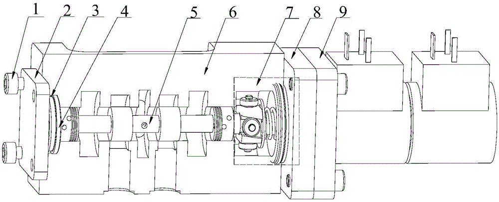
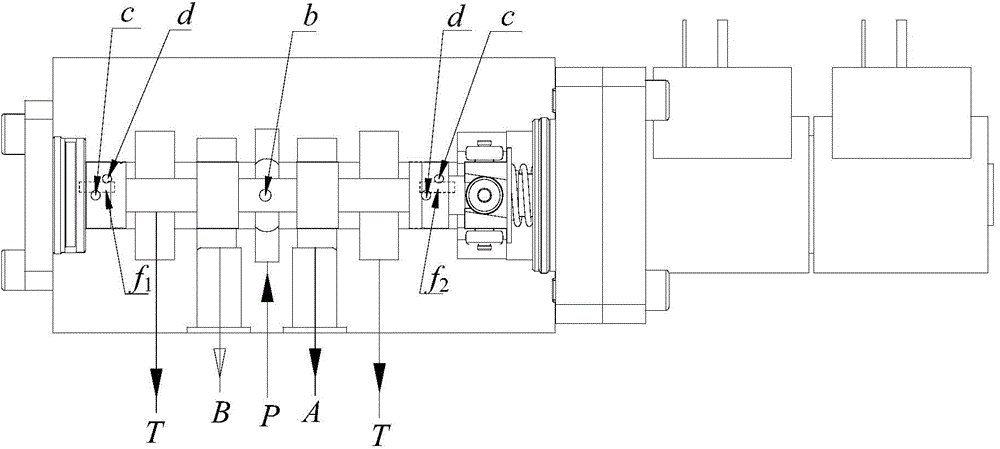
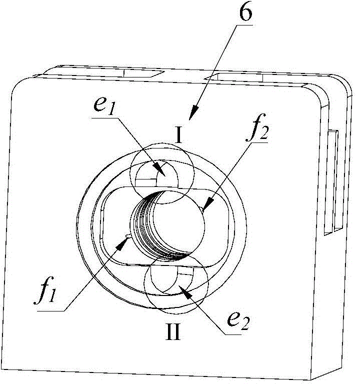
[0028] refer to figure 1 ~Fig. 6, a 2D electro-hydraulic proportional reversing valve with amplified displacement includes screw 1, left cover plate 2, left plug ring 3, O-ring 4, valve core 5, valve body 6, compression torsion assembly 7, end Cover 8, two-way proportional electromagnet 9; spool 5 includes accessory central axis 12, first roller 71 and second roller 72, elastic circlips 61 and 62, inner gaskets 51 and 52, inner spring 11 and elastic retainer Ring 65, press torsion assembly 7 includes wedge 10, third roller 73 and fourth roller 74, circlips 63 and 64, pin 13, large washer 14, outer spring 15, small washer 16 and circlip 17 . The displacement can be amplified 2D electro-hydraulic proportional reversing valve is composed of three parts: 2D valve, bidirectional pressure-torsion coupling and linear electro-mechanical converter.

[0029] The 2D valve part...


PUM

PropertyMeasurementUnit
Diameteraaaaaaaaaa

Abstract

The invention provides a displacement amplifying type 2D electro-hydraulic proportional directional valve. The displacement amplifying type 2D electro-hydraulic proportional directional valve is that the right end of the 2D valve is fixedly connected with a bidirectional electric-mechanical conversion device through a roller type pressing torsion coupling and a pin; a wedge-shaped part is in contact with a central shaft through a roller; a right sensitive cavity is formed between a right circular bead at the end part a valve element, an end cover of the pressing torsion coupling and a valve body; a left sensitive cavity is formed between a left circular bead at the end part of the valve element, a left piston ring and the valve body; high pressure holes are formed in the circular beads at the end parts and are communicated with a P opening through inner holes of the valve element; low pressure holes are formed in the end part of the valve element and directly communicated with the T opening; sensitive channels of which the diameter is in a form of a semicircular section are formed in the upper two ends of the inner hole wall of the valve body; the sensitive channels are respectively communicated with the left sensitive cavity and the right sensitive cavity; the high and low pressure holes in the circular beads in two ends of the valve element are intersected with the sensitive channels to form two micro opening areas which are connected in series to form hydraulic resistance half axles; pressure of the sensitive cavities in two ends is respectively controlled by the hydraulic resistance half axles at two ends.

Description

technical field [0001] The invention belongs to an electro-hydraulic proportional valve in the field of fluid transmission and control, in particular to an electro-hydraulic proportional reversing valve. Background technique [0002] The electro-hydraulic proportional control technology is a hydraulic control technology between the switch-type electro-hydraulic system and the electro-hydraulic servo system. The electro-hydraulic proportional valve is a hydraulic valve that continuously and proportionally controls the pressure, flow and other parameters of the oil according to the input electrical signal. It can not only realize complex control functions, but also has the advantages of strong anti-pollution ability, low cost, and fast response. In hydraulic control engineering, electro-hydraulic proportional directional valves can directly replace electro-hydraulic servo valves for load control in many occasions. Position, speed, and force control, it can be combined with el...

Claims


Application Information

Patent Timeline
IPC IPC(8): F16K11/078F16K31/06
CPCF16K11/078F16K31/06
Inventor 阮健刘国文李胜孙杰陈烜申屠胜男范勇
Owner ZHEJIANG UNIV OF TECH
Why Eureka
Try Eureka