
Device and method for testing stress of infrared optical material

A technology of infrared optical materials and stress testing, which is applied in the direction of measuring the change force of the optical properties of the material when it is stressed, can solve the problems of not meeting the stress test, affecting the quality of thermal imaging, glass bursting, etc., and achieve test efficiency High performance, reliable performance, and the effect of avoiding bursting

Active Publication Date: 2015-04-22
HUBEI NEW HUAGUANG NEW INFORMATION MATERIALS CO LTD
View PDF6 Cites 7 Cited by
  • Summary
  • Abstract
  • Description
  • Claims
  • Application Information

AI Technical Summary

Problems solved by technology

This type of material has a large thermal expansion coefficient, and the high stress will cause the glass to burst during cold processing. In addition, there is stress in the components, which also affects the quality of thermal imaging.
Since this type of material is an infrared optical material that is opaque to visible light, the existing polarizing stress meter (with a test wavelength of 565nm) cannot meet the stress test of this type of material

Method used


Image

  • Device and method for testing stress of infrared optical material
  • Device and method for testing stress of infrared optical material
  • Device and method for testing stress of infrared optical material

Examples


Embodiment Construction

[0025] For being able to further understand technical content, characteristic and effect of the present invention, enumerate following example now, and in conjunction with Attached picture The details are as follows.

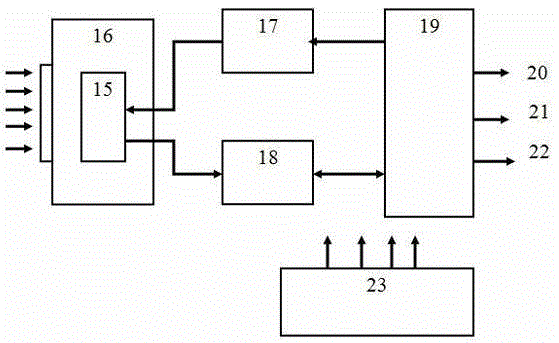
[0026] The present invention provides an infrared optical material stress testing device, which is composed of five parts: an infrared light source 1, an infrared optical system, a signal receiving system 12, a computer acquisition, processing and display system, and a testing platform 7.

[0027] Considering that the tested sample is an infrared optical material with a transmission wavelength range of 0.78-25 μm, the infrared light source 1 is designed to use a point light source, a line light source or a plane light source with an emission spectrum of near and mid-infrared. Generally, single-wavelength infrared laser diode LFO-450 and infrared helium-neon laser light source are selected, and their emission spectrum is λ=1300nm or λ=3390nm; the output power of...


PUM

PropertyMeasurementUnit
thicknessaaaaaaaaaa

Abstract

The invention relates to a device and method for testing the stress of an infrared optical material, belongs to the technical field of infrared optical material test, and aims at solving the problems in testing the stress of the infrared optical material through which visible light cannot be transmitted in the prior art. The device is mainly characterized by comprising an infrared light source, an infrared optical system, a signal reception system, a computer acquisition, processing and display system and a test platform. Test is carried out based on the principle of angular measurement compensation of a polarization analyzer, when an angle of 45 degree is formed between an infrared polarizer and an infrared polarization analyzer, namely a vector stress is include, elliptically polarized light generates a stroke difference, and thus, the stress of the material can be calculated. The device is characterized by simple operation and convenient test, the stress of the infrared optical material, through which visible light cannot be transmitted, can be tested, stress test can be used to guide and optimize production technology, glass of a lower stress can be produced, the imaging quality of the infrared material can be further improved, and a high-level infrared imaging system can be produced on the basis.

Description

technical field [0001] The invention belongs to the technical field of infrared optical material testing, and relates to an infrared optical material stress testing device and a testing method thereof. In the present invention, by designing an infrared optical material stress testing device, the stress of the infrared optical material opaque to visible light can be visualized and measured, especially the stress test of the infrared optical material opaque to visible light with a transmission waveband of 0.78-25 μm. The stress test of the material plays an important role in the manufacture, processing, coating and use of the material. Background technique [0002] Usually, the internal stress of the original isotropic glass material is caused by the difference in the thermal history of the cooling in the manufacturing process of the optical material. When a beam of polarized light is irradiated on a glass material with internal stress, the polarized light can be decomposed i...

Claims


Application Information

Patent Timeline
Patent Type & Authority Applications(China)
IPC IPC(8): G01L1/24
Inventor 胡向平段晓涛唐雪琼徐光以徐华峰
Owner HUBEI NEW HUAGUANG NEW INFORMATION MATERIALS CO LTD
Learn More