Rotor, and vacuum pump equipped with rotor

A vacuum pump and rotor technology, applied in the direction of pumps, parts of pumping devices for elastic fluids, pump elements, etc., can solve the problem of poor balance workability, application of synthetic resin adhesive M1, and balance workability deterioration. and other problems to achieve the effect of improving exhaust performance

Active Publication Date: 2015-04-22
EDWARDS JAPAN
View PDF6 Cites 3 Cited by
  • Summary
  • Abstract
  • Description
  • Claims
  • Application Information

AI Technical Summary

Problems solved by technology

At this time, since the groove D for balancing has a predetermined depth from the inner peripheral surface of the rotor 6, if the tool T inserted as described above is not inclined at a predetermined angle relative to the inner peripheral surface of the rotor 6 (refer to Figure 10 tool T indicated by a solid line), the synthetic resin adhesive M1 cannot be applied to the groove D, an...

Method used


Image

  • Rotor, and vacuum pump equipped with rotor
  • Rotor, and vacuum pump equipped with rotor
  • Rotor, and vacuum pump equipped with rotor

Examples


Embodiment Construction

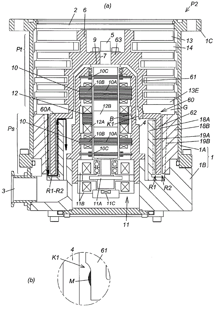
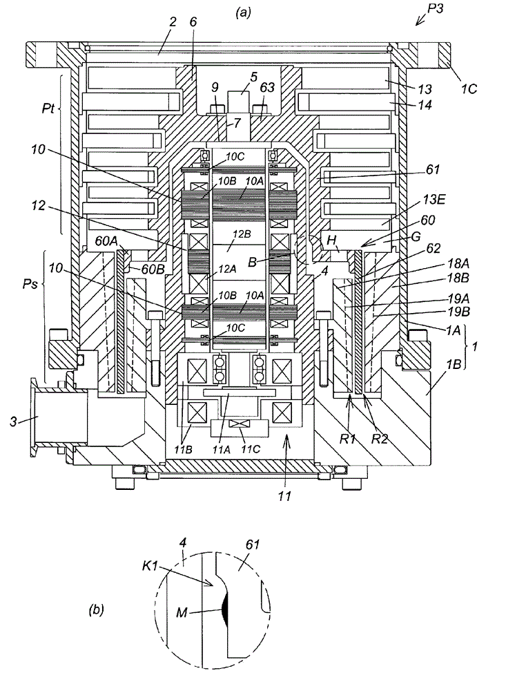
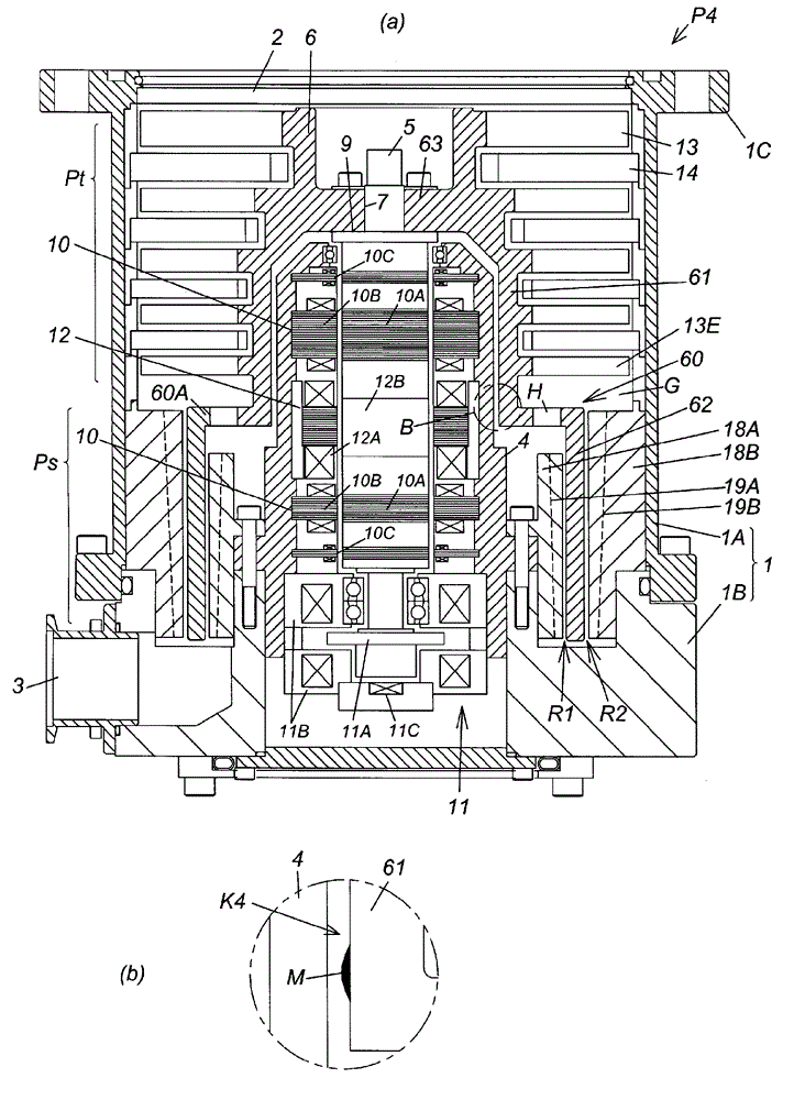
[0046] Below, while referring to the attached Figure 1 A preferred mode for carrying out the present invention will be described in detail.

[0047] figure 1 (a) is a cross-sectional view of a vacuum pump (screw groove pump parallel flow type) as the first embodiment of the present invention, figure 1 (b) is figure 1 (a) Enlarged view of part B.

[0048] Should figure 1 The vacuum pump P1 in (a) is used, for example, as a gas exhaust mechanism in a processing chamber of a semiconductor manufacturing device, a flat panel display manufacturing device, or a solar panel manufacturing device, or other closed chambers. This vacuum pump has a vane exhaust part Pt for exhausting gas through the rotating vane 13 and a fixed vane 14, a screw groove exhaust part Ps for exhausting gas through the screw grooves 19A and 19B, and their driving system in the outer casing 1. .

[0049] The exterior case 1 has a bottomed cylindrical shape in which a cylindrical pump case 1A and a bot...


PUM


Abstract

[Problem] To provide a rotor that improves the evacuation capabilities of a vacuum pump, and that prevents shedding of fragments from a balancing section, and a vacuum pump equipped with this rotor. To provide a rotor for a vacuum pump suited to improving the evacuation capabilities of the vacuum pump and the operability of the balancing section, and that prevents shedding of fragments from the balancing section, or, in the unlikely event that shedding has occurred, affords rapid expulsion and rapid discovery thereof. [Solution] The rotor (6) of a vacuum pump (P1) is provided with first and second cylinders (61, 62) and a linking part (60) linking both of the cylinders (61, 62) together. The first cylinder (61) is provided on the outside peripheral surface with a plurality of rotating blades (13), these rotating blades (13) being arranged in alternating fashion to a plurality of stationary blades along the axial center of the vacuum pump to constitute a bladed evacuation section (Pt). A thread groove evacuation channel (R1) is formed on at least the inside peripheral side of the second cylinder (62), thereby constituting a thread groove evacuation section (Ps). In the rotor (6), a balancing section (K1) for the rotor (6) is furnished on the inside peripheral surface of the first cylinder (61) of the linking part (60), and this balancing section (K1) is furnished with a mass addition means (M).

Description

technical field [0001] The present invention relates to a rotor of a vacuum pump used as a processing chamber of a semiconductor manufacturing device, a flat panel display manufacturing device, a solar panel manufacturing device, and a gas exhaust mechanism of other closed chambers, and a vacuum pump including the rotor. Background technique [0002] As a vacuum pump that exhausts gas in a chamber by rotation of a rotor, for example, a vacuum pump disclosed in Patent Document 1 is known. In such a vacuum pump, it is necessary to balance the entire rotating body including the rotor (8) and the rotating blades (10) integrally provided on the outer peripheral surface thereof during the vacuum pump assembly and manufacturing stage. [0003] In particular, in the case of a vacuum pump that exhausts corrosive gases as in Patent Document 1, since an anti-corrosion film such as nickel-phosphorus plating is formed on the surface of the rotor (8), The region of the film is coated wit...

Claims


Application Information

Patent Timeline
IPC IPC(8): F04D19/04
CPCF04D19/046F04D19/042F04D29/662F04D19/044F05D2260/95F04D29/083F04D19/048F04D29/023F04D29/051F04D29/058F04D29/38
Inventor 大立好伸前岛靖高阿田勉坂口祐幸高井庆行
Owner EDWARDS JAPAN
Why Eureka
Try Eureka