


Quick Research
Generate reliable direction feasibility study reports for your R&D in just a few steps.

Technical Q&A
Discover and master advanced knowledge NOW. Basics, ideas, possibilities, all at once.

Find Solutions
As an expert in R&D theories, this can generate solutions to your technical problems instantly.

Evaluate Feasibility
Analyze your overall solution with one click, know your potential R&D risks in advance.

Monitor Landscape
Get weekly tech updates, stay abreast of the latest tech innovations and key insights.
Integrated active ultrasonic probe
A technology of ultrasonic probe and ultrasonic energy, which is applied in the direction of material analysis, processing detection response signals, and instruments using sound waves/ultrasonic waves/infrasonic waves, and can solve problems such as difficult manipulation and dense cables
- Summary
- Abstract
- Description
- Claims
- Application Information
AI Technical Summary
Problems solved by technology
Method used
Image

Examples
Embodiment Construction
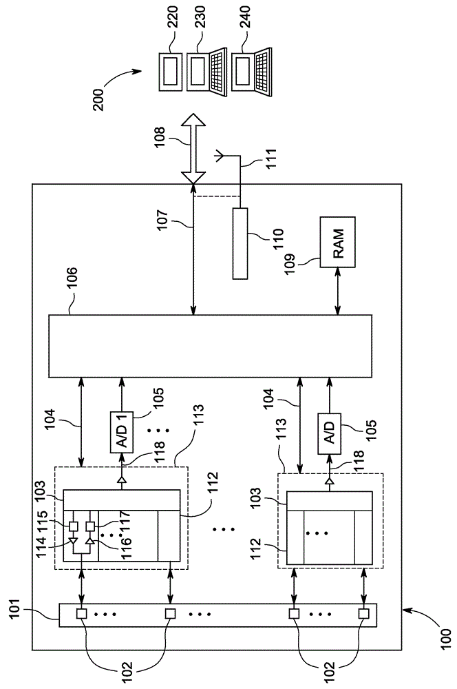
[0016] figure 1 An integrated active ultrasound probe 100 is shown. In one embodiment, an integrated active ultrasound probe 100 includes an array 101 of ultrasound transducers 102 each connected to a transmitter and receiver circuit 112 . The transmitter portions of the transmitter and receiver circuits 112 each include a pulse generator 114 that transmits electrical pulses to the connected ultrasound transducers of the ultrasound transducer 102 . A pulse generator 114 generates electrical pulses that are coordinated by control circuitry 103 and buffered by transmitter delay circuitry 115 (including delays for controlling beam steering).
[0017] The receiver portion of the transmitter and receiver circuit 112 includes: an amplifier 116 ; and a receiver delay 117 for receiving ultrasound echoes detected by one of the connected ultrasound transducers 102 . In addition to controlling the transmitter signals to the ultrasound transducer 102, the control circuit 103 also uses t...
PUM
 Abstract
Description
Claims
Application Information
 - R&D Engineer
- R&D Manager
- IP Professional
- Industry Leading Data Capabilities
- Powerful AI technology
- Patent DNA Extraction
Browse by: Latest US Patents, China's latest patents, Technical Efficacy Thesaurus, Application Domain, Technology Topic, Popular Technical Reports.
© 2024 PatSnap. All rights reserved.Legal|Privacy policy|Modern Slavery Act Transparency Statement|Sitemap|About US| Contact US: help@patsnap.com