Welding slag package suitable for copper slag slow cooling process

A slow cooling and slag ladle technology, applied in manufacturing tools, metal processing equipment, casting melt containers, etc., can solve the problems of production pollution, short service life, high maintenance rate, low maintenance cost, long service life, Weld repair performance is good

Active Publication Date: 2016-08-24
MCC BAOSTEEL TECH SERVICE
View PDF8 Cites 0 Cited by
  • Summary
  • Abstract
  • Description
  • Claims
  • Application Information

AI Technical Summary

Problems solved by technology

[0005] In summary, the foundry slag ladle used in the traditional copper slag treatment process has defects such as high maintenance rate, short service life, serious environmental pollution, and high energy consumption.

Method used


Image

  • Welding slag package suitable for copper slag slow cooling process
  • Welding slag package suitable for copper slag slow cooling process
  • Welding slag package suitable for copper slag slow cooling process

Examples


Embodiment 2

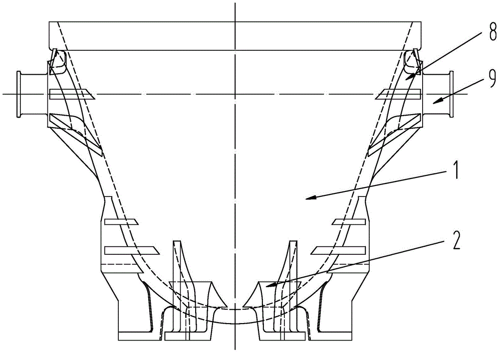
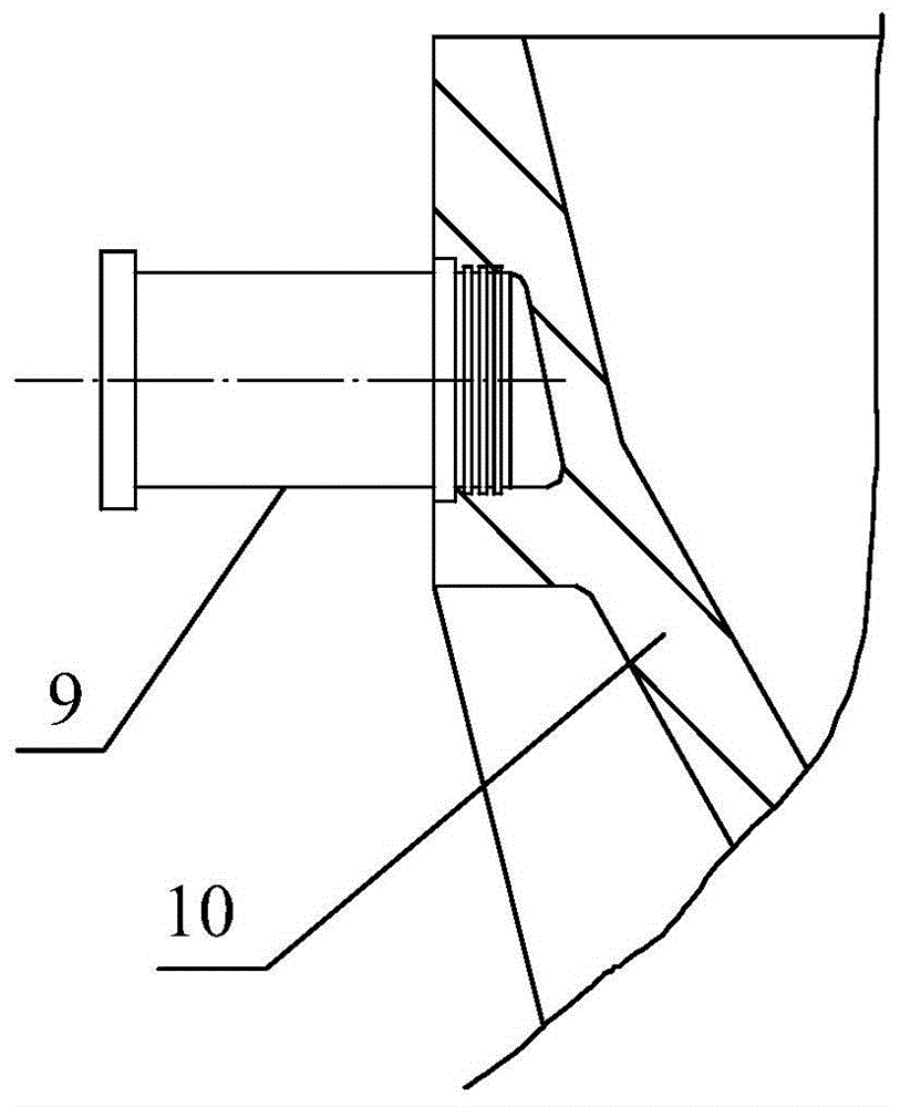
[0090] Embodiment two, see Figure 10 to Figure 12, an upper plate 13, a left plate 14, a lower plate 15, and a right plate 16 are arranged between the trunnion plate 8 and the package body 1, and the upper plate 13, the left plate 14, the lower plate 15, and the right plate 16 are arranged along the ears. The circumferential direction of the shaft 9 is evenly distributed, and the outer peripheries of the upper plate 13 , the left plate 14 , the lower plate 15 and the right plate 16 are all welded with the encasement 1 , the trunnion 9 and the trunnion plate 8 . During installation, four planes perpendicular to each other are milled on the outer peripheral surface of the trunnion 9, the center line is drawn on the trunnion 9, the trunnion 9 and the trunnion plate 8 are assembled together, and then the upper plate 13, The left plate 14, the lower plate 15, and the right plate 16 are respectively stuck on the four planes milled out from the outer peripheral surface of the trunni...

Embodiment 3

[0091] Embodiment three, see Figure 21 to Figure 23 , the inner side of the trunnion plate 8 is provided with a trunnion reinforcing plate 31, the trunnion 9 penetrates into the trunnion plate 8 and the trunnion reinforcing plate 31 in turn, and the trunnion 9 is connected with the trunnion plate 8 and the trunnion reinforcing plate The strong plate 31 is a key connection. In this embodiment, the trunnion 9 and the trunnion plate 8, and the trunnion 9 and the trunnion reinforcing plate 31 are connected by keys 17, and the two sides of the trunnion plate 8 are provided with The side sealing plate 32 connected to the package body 1 is to ensure the strength requirements of the most important parts of the welding slag package. Preferably, a pressure plate 33 is provided on the outer surface of the trunnion plate 8 , the trunnion 9 is penetrated in the pressure plate 33 , and the pressure plate 33 and the trunnion plate 8 are connected by a plurality of fixing bolts 34 . Since t...


PUM

PropertyMeasurementUnit
particle sizeaaaaaaaaaa
thicknessaaaaaaaaaa

Abstract

The invention provides a novel welding slag ladle suitable for a slow cooling process of copper slag. The novel welding slag ladle comprises a ladle body, a ladle bottom and a plurality of ladle feet, wherein the ladle body is pressed into a whole; the ladle bottom is welded at the bottom of the ladle body; the ladle feet are welded at the bottom of the ladle bottom; a radiating space is formed between the two adjacent ladle feet; the ladle body, the ladle bottom and the ladle feet are all made of low-alloy high-strength plates. The novel welding slag ladle does not have any structural change during a using process and is particularly suitable for the slow cooling process of the copper slag; the service life of the welding slag ladle is greatly prolonged, so that the recycling cost of the copper slag is reduced.

Description

technical field [0001] The invention relates to a slag bag used in the copper slag treatment process in the smelting industry, in particular to a welding slag bag suitable for the copper slag slow cooling process. Background technique [0002] With the increasing shortage of copper resources in my country, copper smelting enterprises pay more and more attention to the treatment of copper slag. In the copper slag treatment process, slag ladles are used to transport liquid copper slag, and the slag ladles are casting slag ladles. After the slag bag is loaded with liquid copper slag, the temperature of the slag bag rises rapidly. It is measured that the temperature of the slag bag rises to about 600°C after the liquid copper slag is loaded; then the copper slag is sprayed with water for rapid cooling. In the above process, the slag ladle is subject to extremely cold and extremely hot temperature changes. Due to the limitation of the casting process, the larger the casting slag...

Claims


Application Information

Patent Timeline
Patent Type & Authority Patents(China)
IPC IPC(8): B22D41/00
CPCB22D41/00
Inventor 翟恒东曲登伟郑峰任中立耿会良
Owner MCC BAOSTEEL TECH SERVICE
Why Eureka
Try Eureka