Biomass gasification burner
A burner, biomass technology, applied in the combustion chamber, combustion method, combustion equipment and other directions, can solve the problems of the burner without considering the maintenance port, increase the artificial strength, high temperature gas leakage, etc., to ensure the safety of use and cracking. temperature, increasing safety and service life, effect of increasing service life
- Summary
- Abstract
- Description
- Claims
- Application Information
AI Technical Summary
Problems solved by technology
Method used
Image
Examples
Embodiment 1
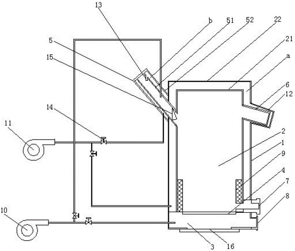
[0058] Example 1, such as figure 1 As shown, a biomass gasification burner includes a furnace body 1. The furnace body 1 is divided into a furnace 2 and an ash chamber 3. A movable fire grate 4 is installed between the furnace 2 and the ash chamber 3, and is set on the furnace body 1. The feeder 5 and burner 6 on the side, the slag outlet 7 and the ash outlet 8 on the lower side of the furnace body 1, and the temperature-resistant layer 9 on the inner wall of the furnace 2, the furnace 2 includes an inner tank 21 and an outer tank 22 , there is a gap a between the inner and outer bladders, the burner 6 and the inner tank 21 are connected through each other, and the outer tank 22 and the burner 6 are welded with a two-layer burner 12 with a similar structure according to the clearance fit method;
[0059] The feeder 5 is divided into an inner layer structure 51 and an outer layer structure 52, and there is a gap b between the inner and outer layer structures. The gap b and the ...
Embodiment 2
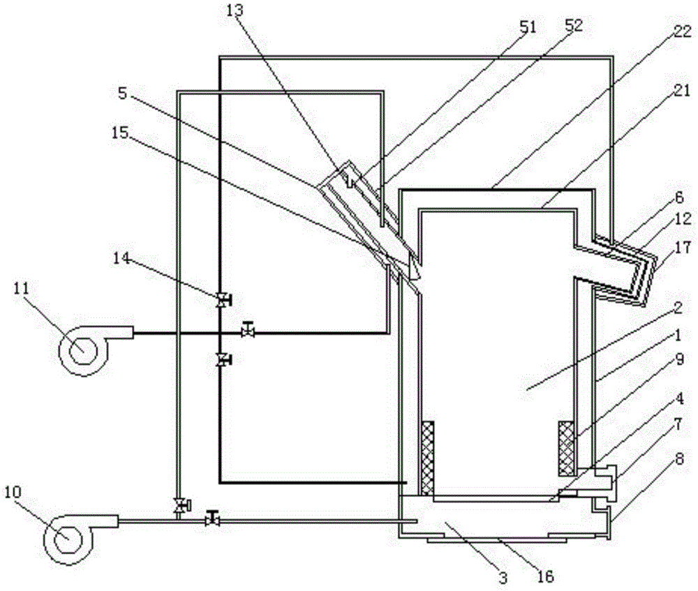
[0073] Example 2, such as figure 2 As shown, it also includes a three-layer burner 17 similar in structure to the two-layer burner 12 welded by clearance fit, and the inner wall of the three-layer burner 17 communicates with the secondary fan 11 through a pipeline.
[0074] The beneficial effect is that the fuel is burnt with oxygen three times, the combustion is more complete, and the burner 6 is cooled to prolong the service life.
Embodiment 3
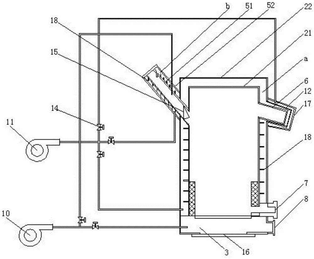
[0075] Example 3, such as image 3 As shown, the air deflector 18 is arranged in both the gap a and the gap b, and the air deflector 18 in the gap a is welded and fixed to the outer wall of the inner tank 21, and the wind deflector 18 in the gap b is welded and fixed to the inner layer structure 51 outer wall.
[0076] Its beneficial effect is: the increase of the air deflector 18 makes the cold air blown into the gap a and the gap b more comprehensive and more regular around the periphery of the inner tank 21 and the periphery of the inner layer structure 51, and the cooling efficiency is higher.
PUM
 Abstract
Description
Claims
Application Information
 - R&D
- Intellectual Property
- Life Sciences
- Materials
- Tech Scout
- Unparalleled Data Quality
- Higher Quality Content
- 60% Fewer Hallucinations
Browse by: Latest US Patents, China's latest patents, Technical Efficacy Thesaurus, Application Domain, Technology Topic, Popular Technical Reports.
© 2025 PatSnap. All rights reserved.Legal|Privacy policy|Modern Slavery Act Transparency Statement|Sitemap|About US| Contact US: help@patsnap.com


