Multi-functional heating furnace

A heating furnace and multi-functional technology, applied in the field of heating furnace, can solve the problems of short service life and achieve the effects of reasonable structure, reduced maintenance time and investment saving

Inactive Publication Date: 2015-04-29
史晨
View PDF0 Cites 6 Cited by
  • Summary
  • Abstract
  • Description
  • Claims
  • Application Information

AI Technical Summary

Problems solved by technology

Effectively prevent the corrosion and scaling of the heating tube, easy to burn out, and short service life. At the same time, the heat exchange cylinder and the heating tube are respectively submerged in the output liquid and the heat transfer medium, so that no heat loss occurs and the heating efficiency is improved.

Method used


Image

  • Multi-functional heating furnace

Examples


Embodiment Construction

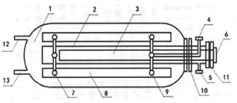
[0017] Such as figure 1 As shown, the multifunctional heating furnace includes a heating furnace shell 1 , a heat exchange cylinder 2 , a heating pipe 3 , and a power interface 6 . There are wing cylinders 8 on both sides of the main cylinder, the main cylinder and the left end of the wing cylinder are connected by a connecting pipe 7, the right end of the wing cylinder is connected with the outlet pipeline 4 at the upper right end of the main cylinder, and there is a circulating nozzle pipeline 5 at the lower right end of the main cylinder , the main cylinder and the shell are connected and sealed with the flange 10, and the main cylinder and the heating pipe are connected and sealed with the flange 11. There is a production fluid inlet pipeline 12 at the upper left end of the housing, and a production fluid outlet pipeline 13 at the bottom.

[0018] According to actual needs, the above multifunctional heating furnace can be further optimized or / and improved:

[0019] as att...


PUM


Abstract

The invention relates to a multi-functional heating furnace. The heating furnace comprises a heating furnace casing, a heat exchange barrel, a heating pipe, water circulating pipes and an external power source, wherein the heating furnace casing is used for storing oil well output liquid; the heat exchange barrel is directly inserted into the heating furnace casing and immersed into the output liquid, the heat exchange barrel consists of a main barrel and two wing barrels, and the main barrel and the two wing barrels are filled with heat-conducting media; the heating pipe is inserted into the main barrel and immersed into the heat-conducting media so as to heat the heat-conducting media; the output liquid is indirectly heated through the heat exchange barrel. According to the multi-functional heating furnace, the problems that the heating pipe is corroded and scaled and easy to burn out and the service life is short are effectively prevented, in addition, the heat exchange barrel and the heating pipe are respectively sunken in the output liquid and the heat-conducting media, so that heat loss is not generated, and the heating efficiency is improved. The heat exchange barrel is connected with a circulating water inlet pipeline and a circulating water outlet pipeline and can be connected with a solar water heater, and heat media preliminarily heated by the solar water heater are transported to the heating pipe to be reheated, so that solar energy resources are effectively utilized, and electric energy is saved. A power source of the heating pipe can be connected with a wind-energy generating battery and a solar battery, so that the comprehensive utilization of wind, light and electricity is realized, the energy is saved, and the emission is reduced. The heat exchange barrel comprises the two wing barrels, the diameter and the length of each wing barrel can be regulated so as to meet requirements of the heat exchange area, the same ends of the main barrel and the wing barrels are communicated through connecting pipes, after being inserted into the main barrel through the connecting pipes, the other ends of the wing barrels penetrate through sealing flanges of the main barrel and the casing, and penetrate out of the main barrel to be connected with a solar heat source, and the other end of the main barrel is connected with the solar heat source through a connecting pipeline, so that the closed cycle is realized.

Description

technical field [0001] The invention relates to a heating furnace, in particular to a multifunctional heating furnace. Background technique [0002] Due to the high freezing point of the production fluid produced in the oil field, the production fluid needs to be heated and then transported by pipeline or transported by vehicle (ship). After the storage tank is pulled and transported, the current methods of heating the output liquid in the storage tank include direct heating of the fire tank, and heating by thermal resistance. The former has certain safety hazards and is not energy-saving; the latter is easy to produce Scaling will affect the thermal efficiency and burn out the electric heating tube, and the replacement and maintenance need to stop production, and the liquid in the storage tank can only be repaired. [0003] At present, small oil storage tanks mainly use electric heating to generate hot water or directly heat the crude oil in the oil storage tank. The main ...

Claims


Application Information

Patent Timeline
Patent Type & Authority Applications(China)
IPC IPC(8): F24H7/00F24J2/04F28D7/12
CPCY02E10/44
Inventor 史晨
Owner 史晨
Why Eureka
Try Eureka