Low-dose energy spectrum CT image denoising method

A CT image, low-dose technology, applied in image enhancement, image analysis, image data processing, etc., can solve problems such as long reconstruction time, difficulty in satisfying real-time interaction, and large amount of calculation

Active Publication Date: 2015-04-29
SOUTHERN MEDICAL UNIVERSITY
View PDF3 Cites 22 Cited by
  • Summary
  • Abstract
  • Description
  • Claims
  • Application Information

AI Technical Summary

Problems solved by technology

Due to the large amount of spectral CT projection data, this method has too much calculation and very long re

Method used


Image

  • Low-dose energy spectrum CT image denoising method
  • Low-dose energy spectrum CT image denoising method
  • Low-dose energy spectrum CT image denoising method

Examples


Embodiment 1

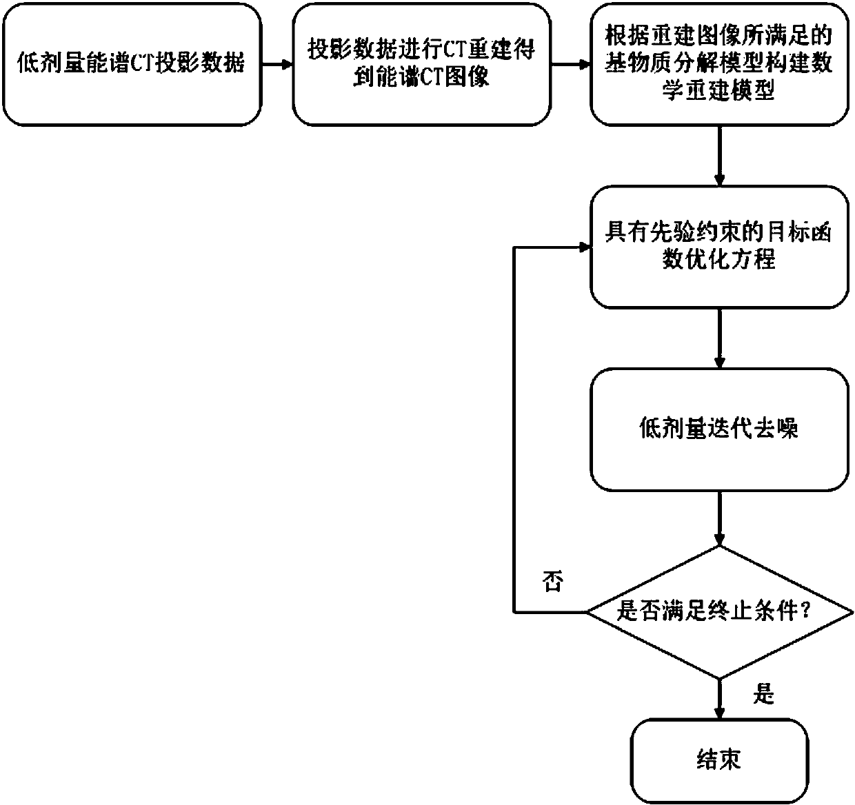
[0047] A low-dose spectral CT image denoising method, such as figure 1 shown, including the following steps,

[0048] (1) Obtain low-energy CT projection data and high-energy CT projection data of the imaging object under low-dose radiation, and perform CT image reconstruction on the low-energy CT projection data and high-energy CT projection data respectively to obtain low-energy CT images and high-energy CT images ,in H means high energy, L Indicates low energy;

[0049] (2) Construct a mathematical model for spectral CT image denoising according to the matrix decomposition model satisfied by the reconstructed data in step (1);

[0050] (3) Using generalized total variation as a regularization prior, combined with the mathematical model obtained in step (2) to construct an objective function for image denoising;

[0051] (4) The objective function for spectral CT image denoising constructed in step (3) is solved by using the split Bregman algorithm to complete the ene...

Embodiment 2

[0075] Taking the digital phantom data of computer simulation as an example to describe the specific implementation process of the method of the present invention, as figure 1 As shown, the implementation process of this embodiment is as follows.

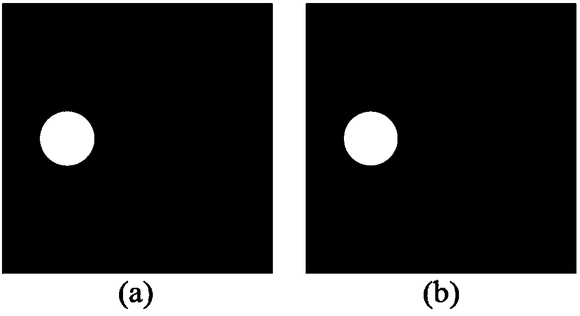
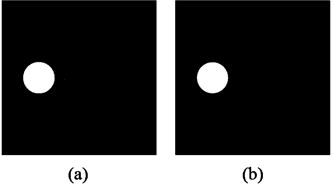
[0076] (1) Use the Clock digital phantom to simulate and generate low-dose spectral CT projection data for verification and evaluation of the algorithm of the present invention. In this embodiment, the distances from the X-ray source of the simulated CT machine to the rotation center and the detector are: 570.00mm and 1040.00mm respectively, the number of detection elements is 672, the size is 1.407mm, and the number of detection angular samples for one rotation for 1160. The Clock phantom image size is 512×512. The projection data of 80kVp and 140kVp with the size of 1160×672 were respectively generated by CT system simulation. The variance of the electronic noise of the system is 10.0.

[0077] (2) Data reconstruction: Use th...


PUM


Abstract

The invention discloses a low-dose energy spectrum CT image denoising method. The low-dose energy spectrum CT image denoising method includes the steps of (1) obtaining low-energy CT projection data and high-energy CT projection data of an imaged object under low-dose rays, carrying out CT image reconstruction on the low-energy CT projection data and the high-energy CT projection data to obtain a low-energy CT image (please see the specification) and a high-energy CT image (please see the specification), wherein H represents high energy, and L represents low energy; (2) building a mathematical model used for energy spectrum CT image denoising according to a base material decomposition model met by the reconstructed data in the step (1); (3) using generalized total variation as regularization prior, and building an objective function used for image denoising in cooperation with the mathematical model obtained in the step (2); (4) solving the objective function which is built in the step (3) and used for energy spectrum CT image denoising with a splitting Bregman algorithm, and completing energy spectrum CT image denoising. According to the low-dose energy spectrum CT image denoising method, the base material decomposition model met by the high-energy image and the low-energy image in an energy spectrum CT is used, energy spectrum CT image information and base material image information are combined, and energy spectrum CT image denoising is achieved.

Description

technical field [0001] The invention relates to an image processing method of medical images, in particular to a low-dose energy spectrum CT image denoising method. Background technique [0002] With the rapid development of CT technology, dual-energy CT scanning technology based on spectral integration detectors and photon counting detection technology based on energy-resolution detectors have enabled spectral CT imaging to be realized. Spectral CT is one of the development directions of CT imaging technology in the future, because spectral CT can not only obtain the information of the internal attenuation coefficient of the material, but also obtain the information of the material composition through reconstruction. Spectral CT can transfer from traditional morphological diagnosis to functional diagnosis. For example, it can find lesions that cannot be found by conventional CT, realize ultra-early detection of tumors, and perform qualitative diagnosis and quantitative anal...

Claims


Application Information

Patent Timeline
IPC IPC(8): G06T7/00
CPCG06T5/002G06T2207/10081G06T2207/20172
Inventor 马建华曾栋边兆英黄静陈武凡
Owner SOUTHERN MEDICAL UNIVERSITY
Why Eureka
Try Eureka