
Microwave ultraviolet lamp based on electron cyclotron resonance principle

A technology of electron cyclotron resonance and ultraviolet lamps, which is applied to the components and circuits of discharge lamps and gas discharge lamps. It can solve the problems of low luminous efficiency, poor UV curing effect, long start-up time, etc. Good curing effect and shortened start-up time

Inactive Publication Date: 2015-04-29
HARBIN UNIV OF SCI & TECH +1
View PDF4 Cites 2 Cited by
  • Summary
  • Abstract
  • Description
  • Claims
  • Application Information

AI Technical Summary

Problems solved by technology

[0004] In order to solve the problem of low luminous efficiency caused by the long start-up time of the middle part of the existing microwave ultraviolet lamp tube, and also to solve the problem of poor ultraviolet curing effect of this lamp, the present invention proposes a microwave based on the principle of electron cyclotron resonance UV lamp

Method used


Image

  • Microwave ultraviolet lamp based on electron cyclotron resonance principle
  • Microwave ultraviolet lamp based on electron cyclotron resonance principle
  • Microwave ultraviolet lamp based on electron cyclotron resonance principle

Examples


specific Embodiment approach 1

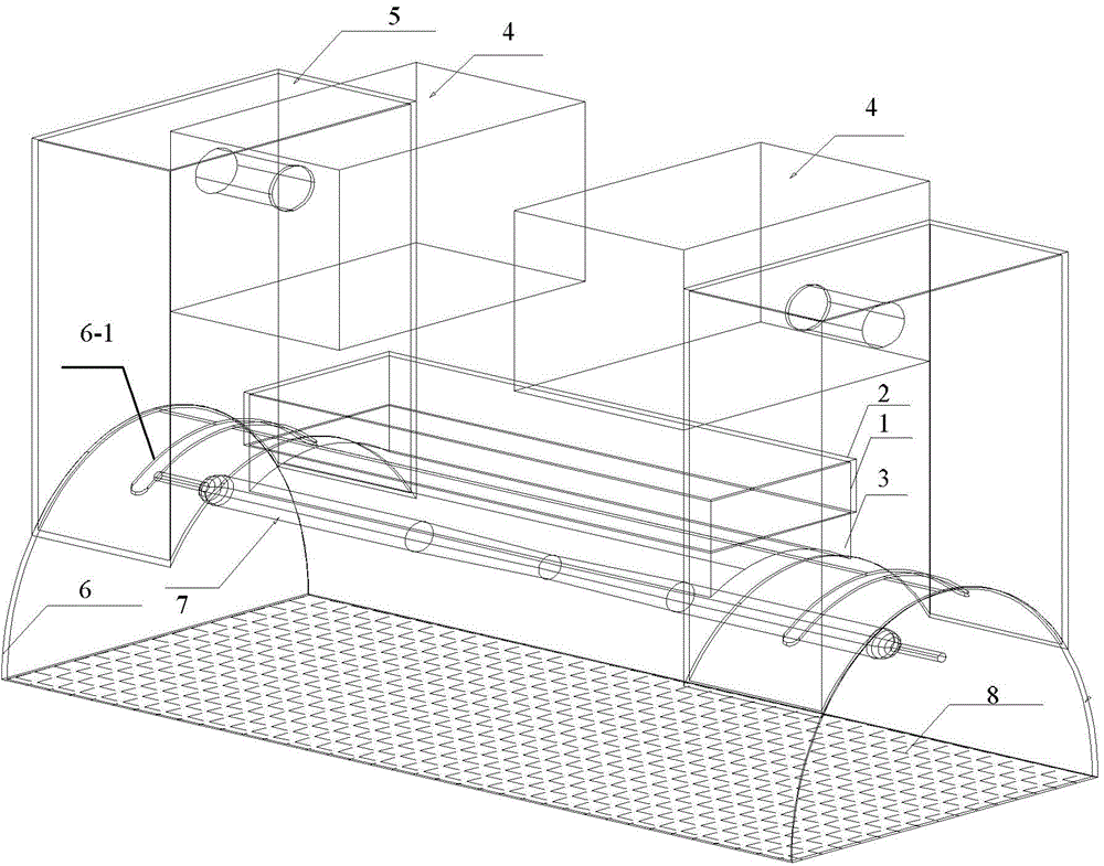
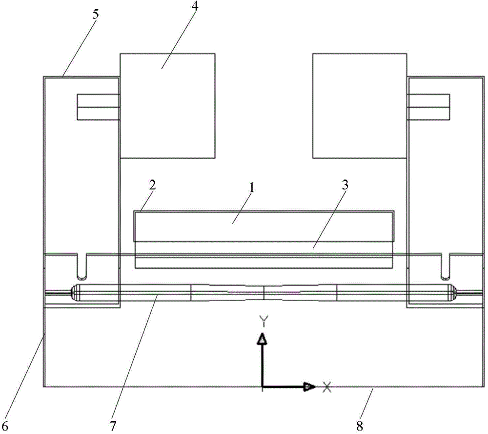
[0020] Specific implementation mode 1, refer to figure 1 , figure 2 , image 3 , Figure 4 , Figure 5 and Figure 7 Describe this embodiment in detail, a kind of microwave ultraviolet lamp based on electron cyclotron resonance principle described in this embodiment, it comprises magnetron 4, magnetron excitation cavity 5 and lamp tube 7, and magnetron 4 is used for its The emitted microwave is injected into the magnetron excitation cavity 5; it also includes a permanent magnet 1, a permanent magnet protective shell 2, an asbestos board 3, a reflector 6 and a metal shielding net 8;

[0021] The metal shielding net 8 is fixed on the bottom of the reflector 6, and the metal shielding net 8 and the reflector 6 form a microwave resonant cavity; the lamp tube 7 is fixed in the microwave resonant cavity, and the central axis of the lamp tube 7 and the transverse axis of the reflector are at the same plane, and the lamp tube 7 is placed along the first focal axis of the reflect...

specific Embodiment approach 2

[0031] Specific embodiment 2. This specific embodiment is a further description of a microwave ultraviolet lamp based on the principle of electron cyclotron resonance described in specific embodiment 1. In this embodiment, the permanent magnet 1 is made of NdFeB permanent magnet. magnet.

[0032] The permanent magnet 1 is N35 NdFeB permanent magnet material, its remanence is 1.2T (Tesla), and the remanence direction is along the Y-axis direction, such as Figure 5 shown. The bottom surface of the permanent magnet 1 is 30mm away from the focal axis of the reflector 6, and the size of the permanent magnet 1 is as follows: Figure 4 shown.

specific Embodiment approach 3

[0033] Specific Embodiment Three. This embodiment is an example.

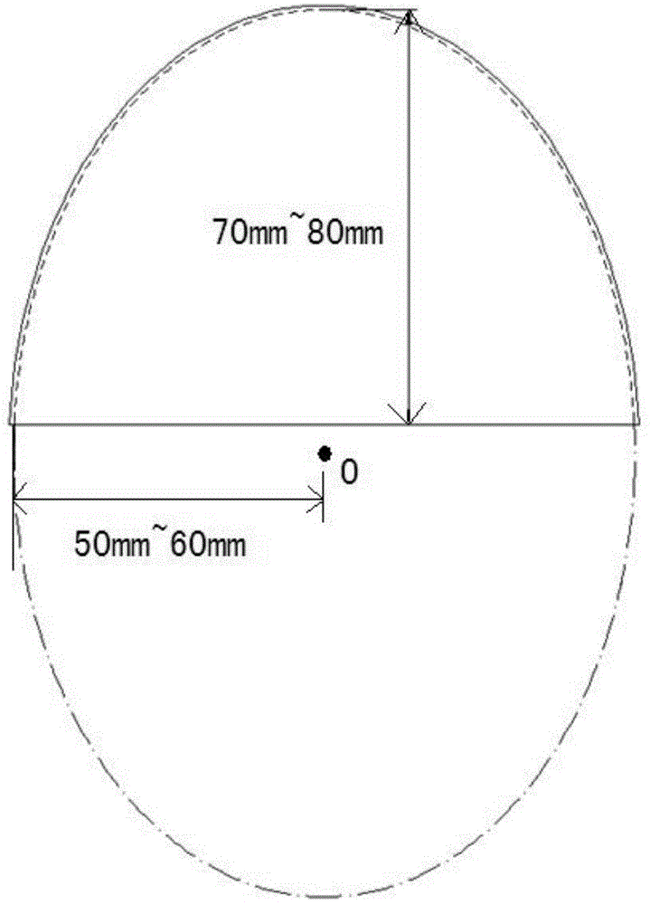
[0034] The semi-major axis of the reflector 6 is 71.8mm, the semi-minor axis is 53.9mm, and the thickness is 0.8mm; the length of the feeding port on the upper surface of the reflector 6 is 60mm, and the width is 5mm.

[0035] The constant magnetic field produced by the permanent magnet 1 at the central axis of the lamp tube 7 is as Image 6 shown. From Image 6 It can be seen from the figure that on the 80mm length of the middle part of the lamp tube 7, the constant magnetic field strength is between 850Gs-900Gs, which is close to 875Gs, which meets the technical requirements proposed by the present invention and can well solve the problem of lamp tubes existing in the prior art. The middle part has problems such as long start-up time and low luminous efficiency.

[0036] The principle of electron cyclotron resonance means that when the electron cyclotron frequency is equal to the microwave frequency used, th...


PUM


Abstract

The invention relates to a microwave ultraviolet lamp based on an electron cyclotron resonance principle, and belongs to the field of microwave electrodeless lightening technology. The microwave ultraviolet lamp based on the electron cyclotron resonance principle is used for solving the problems in the prior art that the starting time of the middle portion of a microwave ultraviolet lamp is long and the luminous efficiency is low. According to the microwave ultraviolet lamp based on the electron cyclotron resonance principle, a modulator tube ia arranged on a microwave resonant cavity which is formed by a reflector and a metal shielding net, a permanent magnet is arranged on the outside surface of the reflector, and the permanent magnet and the modulator tube are arranged on the same straight line. A feed inlet is formed in the reflector, the microwave emanated from a magnetron enters the reflector through an incentive cavity of the magnetron and the feed inlet, a constant magnetic field is generated around the modulator tube by the permanent magnet when the microwave enters the reflector, the coupling of the constant magnetic field and the microwave entering the reflector enables the middle portion inside the modulator tube to generate an electronic resonant acceleration, so that the middle portion of the modulator tube can be started in a relatively short time, and the problems that the starting time of the middle portion of the microwave ultraviolet lamp is long and the luminous efficiency is low and the like are solved. The microwave ultraviolet lamp based on the electron cyclotron resonance principle can be utilized in the fields of the ultraviolet sterilization, the fluorescence excitation, and the relevant ultraviolet curing and the like.

Description

technical field [0001] The invention belongs to the technical field of microwave electrodeless light sources. Background technique [0002] Microwave UV lamp is a new type of high-efficiency electrodeless UV light source. The working principle of the microwave ultraviolet lamp is as follows: First, the high-frequency and high-power microwave generated by the microwave source enters the closed resonant cavity composed of the reflector and the metal shielding net from the feeding port of the reflector through the magnetron excitation cavity. A strong electromagnetic field is generated inside the lamp tube (filled with argon and mercury), and the argon in the lamp tube is first broken down to make it discharge. Since the sub-pressure stable excited state energy of argon is slightly higher than the ionization energy of mercury, it helps to produce the Penning effect, and then effectively ionizes mercury, making it into high-energy mercury ions. When high-energy mercury ions tra...

Claims


Application Information

Patent Timeline
Patent Type & Authority Applications(China)
IPC IPC(8): H01J65/04H01J61/54
CPCH01J65/044H01J61/54
Inventor 赵洪陈俊岐孙崐
Owner HARBIN UNIV OF SCI & TECH
Learn More