Intelligent high-voltage inverter cooling control system

A high-voltage inverter, cooling control technology, applied in cooling/ventilation/heating renovation, power electronics modification, output power conversion device, etc. Cooling and cooling requirements, prolonging service life, and ensuring the effect of work efficiency

Inactive Publication Date: 2015-04-29
CHENGDU JUNHE TIANCHENG TECH
View PDF6 Cites 13 Cited by
  • Summary
  • Abstract
  • Description
  • Claims
  • Application Information

AI Technical Summary

Problems solved by technology

[0002] Generally, the temperature requirement for the installation environment of high-voltage inverters is -5°C to 40°C. The working state ensures that the internal temperature of the cabinet of the high-voltage inverter is lower than 65°C, and the high-voltage inverter generates a lot of heat when it is working, which leads to an increase in the temperature of the equipment and the environment. , affect the normal operation of the equipment, increase the failure rate and decrease the service life
Existing cooling systems have their own advantages and disadvantages in terms of cooling efficiency, energy consumption control, and environmental constraints: the air-conditioning cooling system can quickly and efficiently cool and dehumidify, but it is limited by space, and the working efficiency is low when the external temperature is high, and the energy consumption is high. Large energy; the air cooling system has a simple structure and low cost, but the cooling efficiency is low, the maintenance cost is high, and the stability is highly dependent on the surrounding environment; the main body water cooling system has a good heat dissipation effect, but it has high requirements for the system process, complicated installation, and water leakage Greater hidden danger

Method used


Image

  • Intelligent high-voltage inverter cooling control system
  • Intelligent high-voltage inverter cooling control system
  • Intelligent high-voltage inverter cooling control system

Examples


Embodiment 1

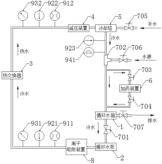
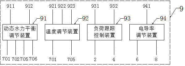
[0030] A high-voltage inverter intelligent cooling control system in this embodiment, such as figure 1 As shown, the circulating water cooling system includes a monitoring system 9 and a circulating water tank 1, a circulating water pump 2, a heat exchanger 3, a decompression device 4, and a cooling tower 5 connected in sequence; the circulating water cooling system also includes a valve 7; The monitoring system 9 includes an external detection instrument, a control system and a valve; the external detection instrument is arranged at both ends of the heat exchanger 3 and the water outlet of the cooling tower 5; the control system includes a dynamic hydraulic balance adjustment device 91 , a temperature regulating device 92 , a load following control device 93 , and a conductivity regulating device 94 . A three-way valve 702 is also arranged between the cooling tower 5 and the circulating water tank 1, and the three-way valve 702 is connected with the circulating water tank 1 i...

Embodiment 2

[0035] In this embodiment, after the dynamic hydraulic balance adjustment device 91 in the monitoring device collects and analyzes the parameters of the flowmeter, it is found that the flow rate at the inlet of the heat exchanger is smaller than the flow rate at the outlet, and the valve A701 is increased. If the water level in the circulating water tank is insufficient, it needs to be opened. Valve F706 allows the water source to replenish. Other parts of this embodiment are the same as those of Embodiment 1, and will not be repeated here.

Embodiment 3

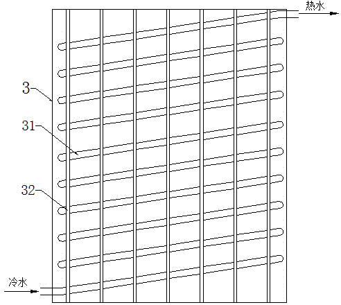
[0037] In this embodiment, an air cooling system is added on the basis of Embodiment 1. The fan blows cold air at 25°C from the air cooling device into the high-voltage inverter. The cold air absorbs heat and becomes hot air. The temperature in the high-voltage inverter cabinet is not higher than 55 ℃, on the one hand, the hot air increases the temperature of the cooling fins 32, and the cooling water pipe 31 passing through the cooling fins 32 absorbs the heat of the hot air and turns it into hot water. After passing through the cooling tower 5, the cooling water drops below 30 °C, and then stands still to about 25°C; on the other hand, the hot air enters the air duct through the fan on the top of the cabinet, and the axial flow fan 12 blows the hot air to the cooling tower 5, the cold water is from top to bottom, and the hot air is from bottom to top to realize heat exchange. Other parts of this embodiment are the same as those of Embodiment 1, and will not be repeated here. ...


PUM


Abstract

The invention discloses an intelligent high-voltage inverter cooling control system. The intelligent high-voltage inverter cooling control system comprises a field bus control system, and an air conditioner cooling system, an air cooling system and a circulating water cooling system which are respectively connected with the field bus control system, wherein the circulating water cooling system comprises a monitoring system (9), a valve (7), and a circulating water tank (1), a circulating water pump (2), a heat exchanger (3), a pressure reducing device (4) and a cooling tower (5) which are sequentially connected; the monitoring system (9) comprises external detection instruments and a control system; the external detection instruments are distributed at two ends of the heat exchanger (3) and the water outlet end of the cooling tower (5); and the control system comprises a dynamic hydraulic balance adjustment device (91), a temperature regulation device (92), a load tracking control device (93) and a conductivity regulation device (94). According to the independent control of the field bus control system on the air conditioner cooling system, the air cooling system and the circulating water cooling system, the cooling mode can be optimized according to actual conditions, and the system disclosed by the invention is intelligent, high-efficiency, energy-saving and stable.

Description

technical field [0001] The invention relates to a cooling control system, in particular to an intelligent cooling control system for a high-voltage frequency converter. Background technique [0002] Generally, the temperature requirement for the installation environment of high-voltage inverters is -5°C to 40°C. The working state ensures that the internal temperature of the cabinet of the high-voltage inverter is lower than 65°C, and the high-voltage inverter generates a lot of heat when it is working, which leads to an increase in the temperature of the equipment and the environment. , affecting the normal operation of the equipment, increasing the failure rate and decreasing the service life. Existing cooling systems have their own advantages and disadvantages in terms of cooling efficiency, energy consumption control, and environmental constraints: the air-conditioning cooling system can quickly and efficiently cool and dehumidify, but it is limited by space, and the work...

Claims


Application Information

Patent Timeline
Patent Type & Authority Applications(China)
IPC IPC(8): H02M1/00H05K7/20
CPCH02M1/00H05K7/2089
Inventor 周洁
Owner CHENGDU JUNHE TIANCHENG TECH
Why Eureka
Try Eureka