Relaxation oscillator

A relaxation oscillator and oscillation circuit technology, applied in the direction of electric pulse generator circuit, differential amplifier to generate pulse, pulse technology, etc., can solve the problems of clock frequency reduction, transistor mobility decrease, increase, etc., to eliminate the influence and improve Frequency stability, effect of reducing temperature sensitivity

Active Publication Date: 2015-04-29
GIGADEVICE SEMICON (BEIJING) INC
View PDF3 Cites 17 Cited by
  • Summary
  • Abstract
  • Description
  • Claims
  • Application Information

AI Technical Summary

Problems solved by technology

For example, when the temperature increases, the mobility of the transistor decreases, resulting in a delay time T d Increase, the clock frequency decreases, thus affecting the frequency stability of the oscillator

Method used


Image

  • Relaxation oscillator
  • Relaxation oscillator
  • Relaxation oscillator

Examples


Embodiment 1

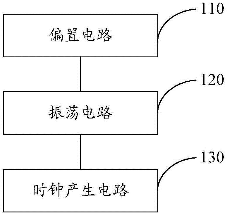
[0041] refer to image 3 , which shows a structural block diagram of an embodiment of a relaxation oscillator in the present invention, which may specifically include:

[0042] A bias circuit 110, configured to generate a bias current, and provide a charging current for the oscillator circuit through the bias current;

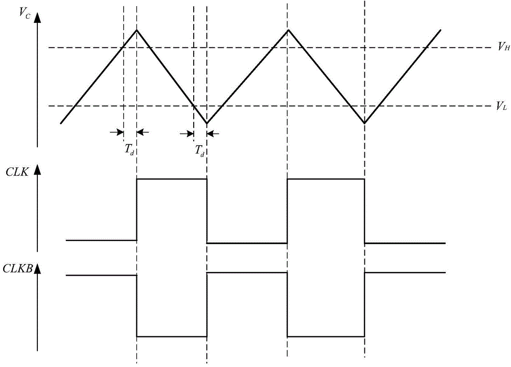
[0043] The oscillation circuit 120 is connected to the bias circuit, and is used to integrate the charging current with a capacitor to generate an integrated voltage, generate a reset pulse according to the integrated voltage, and input the reset pulse to the clock generation circuit; as well as

[0044] A clock generating circuit 130, connected to the oscillating circuit, is used to generate a clock signal through the reset pulse, and control switching of switches in the oscillating circuit through the clock signal, so that the oscillating circuit is alternately charged or discharge.

[0045] The relaxation oscillator of the present invention adopts the met...

Embodiment 2

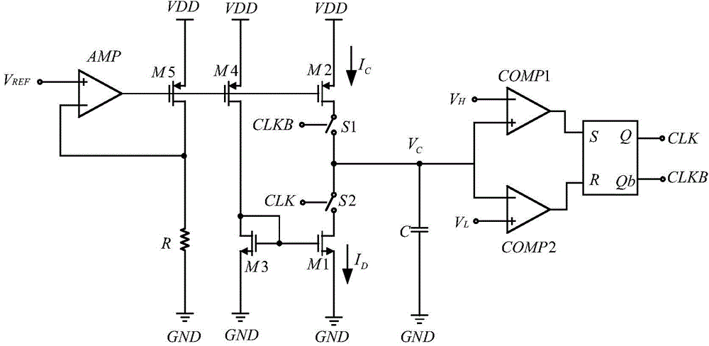
[0047] In order to illustrate the relaxation oscillator proposed by the present invention more clearly, the circuit structures of the bias circuit, the oscillation circuit, and the clock generation circuit will be introduced in detail below.

example 1

[0049] refer to Figure 4 , shows a schematic circuit diagram of a bias circuit of the present invention, the bias circuit may specifically include: a first NMOS transistor M1, a second NMOS transistor M2, a third PMOS transistor M3, a fourth PMOS transistor M4, a first a resistor R1, a second resistor R2, and a power supply VDD;

[0050] Wherein, the gate of M1 is connected to the source of M2, the source of M1 is grounded, the gate of M2 is connected to the drain of M1 and the drain of M3, and the drain of M2 is connected to the drain and gate of M4;

[0051] M3 and M4 form a mirror transistor of a current mirror, the gate of M3 and the gate of M4 are interconnected and connected to the drain of M4, and the source of M3 and the source of M4 are both connected to the power supply VDD;

[0052] R1 and R2 are connected in series, one end of R1 is connected to the source of M2 and the gate of M1, the other end of R1 is connected to one end of R2, and the other end of R2 is grou...


PUM


Abstract

The invention provides a relaxation oscillator. The relaxation oscillator comprises a biasing circuit, an oscillation circuit and a clock generation circuit, wherein the biasing circuit is used for producing biasing current and providing charging current for the oscillation circuit through the biasing current; the oscillation circuit is connected with the biasing circuit and is used for integrating the charging current by using a capacitor so as to produce integrator voltage; reset pulse is produced according to the integrator voltage and is input into the clock generation circuit; the clock generation circuit is connected with the oscillation circuit and is used for producing a clock signal through the reset pulse and controlling the switching of a switch in the oscillation circuit through the clock signal, so that the oscillation circuit can alternately charge or discharge. According to the relaxation oscillator, the frequency stability of the relaxation oscillator can be improved.

Description

technical field [0001] The invention relates to the field of integrated circuits, in particular to a relaxation oscillator. Background technique [0002] For an integrated system on a chip (SOC, System-On-a-Chip), using an on-chip oscillator to generate a clock signal can replace an external crystal, significantly reducing system complexity and cost. The relaxation oscillator has the advantages of simple structure, easy integration and relatively low power consumption. It is a clock generation circuit widely used in oscillators. [0003] Frequency stability is one of the most important performance indicators of an oscillator. In the SOC, the unstable clock will cause the confusion of the timing relationship, which will cause the SOC to fail to work normally. [0004] refer to figure 1 , which shows a schematic structural diagram of a relaxation oscillator in the prior art, which may specifically include an amplifier AMP, a resistor R, PMOS transistors M2, M4 and M5, NMOS ...

Claims


Application Information

Patent Timeline
Patent Type & Authority Applications(China)
IPC IPC(8): H03K3/023H03K3/011
Inventor 刘三林刘志
Owner GIGADEVICE SEMICON (BEIJING) INC
Why Eureka
Try Eureka