
Method for controlling deformation generated when connection pipe is welded to large-diameter thin-wall barrel

A thin-walled cylinder, welding deformation technology, used in welding equipment, auxiliary welding equipment, welding/cutting auxiliary equipment, etc. Small welding deformation, the effect of solving the collapse

Active Publication Date: 2015-05-06
DONGFANG BOILER GROUP OF DONGFANG ELECTRIC CORP
View PDF11 Cites 20 Cited by
  • Summary
  • Abstract
  • Description
  • Claims
  • Application Information

AI Technical Summary

Problems solved by technology

[0004] In order to overcome the existing problems of relatively large deformation and difficult correction when welding the connecting pipe on a thin-walled large-diameter cylinder, the technical problem to be solved by the present invention is to provide a control large-diameter thin-walled cylinder with a small actual deformation. The Method of Welding Deformation of Nozzles on Body

Method used


Image

  • Method for controlling deformation generated when connection pipe is welded to large-diameter thin-wall barrel
  • Method for controlling deformation generated when connection pipe is welded to large-diameter thin-wall barrel
  • Method for controlling deformation generated when connection pipe is welded to large-diameter thin-wall barrel

Examples

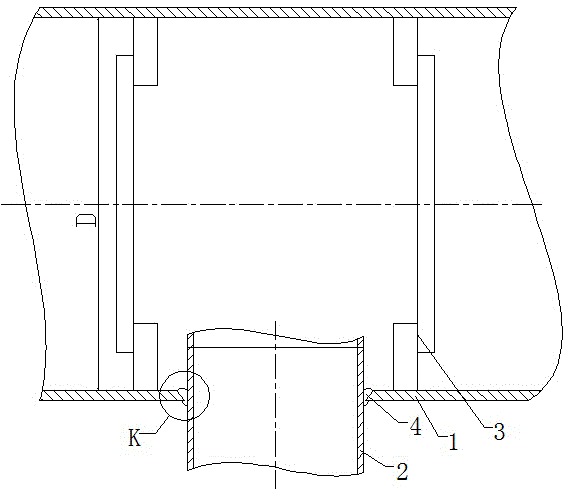
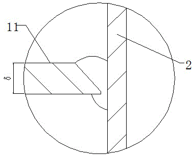
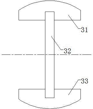

Embodiment

[0026] A connecting pipe with a diameter of 1000mm is to be welded on a pre-rectification column, the material of the cylinder is Q345R, the diameter is φ3000mm, and the wall thickness is 14mm.

[0027] like figure 1 , figure 2 , image 3 , Figure 4 and Figure 5 As shown, the connecting groove 2 is opened on the cylinder body 1, the connecting groove 4 adopts the inner groove, and the internal support 3 is added inside the cylinder body 1, and the form of the internal support 3 is as follows image 3 , Figure 4 As shown, an inner support 3 is installed on the cylinder body 1 on both sides of the connecting pipe 2. After the connecting pipe 2 is adjusted in place, it is connected with the cylinder body 1 by spot welding, and then the connecting pipe 2 is turned to the bottom of the cylinder body 1.

[0028] like Figure 5 As shown, the entire circular weld 5 is divided into eight arc-shaped segmented welds, namely A1 segment, A2 segment...A8 segment, and each segmente...


PUM


Abstract

The invention relates to the field of thin-wall workpiece welding and discloses a method for controlling deformation generated when a connection pipe is welded to a large-diameter thin-wall barrel. According to the method, the amount of actual deformation is small. When the large-diameter thin-wall barrel is welded to the connection pipe connected with the large-diameter thin-wall barrel, an inner groove is adopted as a connection pipe groove in the barrel, and the two sides of the connection pipe groove in the barrel are provided with inner supports used for supporting the inner wall of the barrel; after the connection pipe is connected with the barrel through spot welding, the position of the connection pipe is adjusted, so that the connection pipe is located below the barrel, a circumferential welding line of the connection pipe is divided into an even number of welding line segments, welding of each welding line layer is completed through two rounds of segmented symmetry welding, welding of a half of each welding line segment in the length direction is completed in each round of segmented symmetry welding, and the next layer is welded after all the welding line segments on the upper layer are welded. The whole welding line is divided into a plurality of regions, a layered and regional welding sequence of the welding line is worked out, and therefore heat input is controlled well, welding deformation is reduced, and the problems that the large-diameter connection pipe droops and the barrel deforms are solved.

Description

technical field [0001] The invention relates to a welding method when welding a connecting pipe on a cylindrical body, in particular to a welding deformation control method when welding a connecting pipe on a large-diameter thin-walled cylindrical body. Background technique [0002] At present, in the field of coal gasification, environmental protection equipment and other chemical industries, there are a large number of thin-walled cylinders, and most of these cylinders have thin walls and large diameters. Generally, their diameter / wall thickness ratio is above 120. These cylinders There are different numbers of large-diameter connecting pipes on the surface, these connecting pipes are mainly forgings, and the weight is relatively large. When welding such connecting pipes on the cylinder, manual welding is usually used, and the connecting pipes are placed on the top of the cylinder for welding. It often causes different degrees of nozzle collapse and cylinder deformation. ...

Claims


Application Information

Patent Timeline
Patent Type & Authority Applications(China)
IPC IPC(8): B23K37/053
CPCB23K37/053
Inventor 李占雷银润邦罗永飞张涛朱超兵
Owner DONGFANG BOILER GROUP OF DONGFANG ELECTRIC CORP
Learn More