Burning Apparatus and Method for Manufacturing Reduced Iron Using the Same

A technology of combustion equipment and reduced iron, applied in the direction of lighting and heating equipment, maintenance of heating chamber, improvement of process efficiency, etc., can solve the problem of difficult control of combustion furnace temperature and oxygen concentration, difficulty in mass production of reduced iron, metallization of reduced iron Low rate and other issues

Inactive Publication Date: 2015-05-06
POHANG IRON & STEEL CO LTD
View PDF7 Cites 8 Cited by
  • Summary
  • Abstract
  • Description
  • Claims
  • Application Information

AI Technical Summary

Problems solved by technology

[0004] However, it takes much time to generate a reducing atmosphere inside the combustion furnace, so there is a problem that mass production of reduced iron is difficult
However, since such a process is performed in an open combus

Method used


Image

  • Burning Apparatus and Method for Manufacturing Reduced Iron Using the Same
  • Burning Apparatus and Method for Manufacturing Reduced Iron Using the Same
  • Burning Apparatus and Method for Manufacturing Reduced Iron Using the Same

Examples


example 1

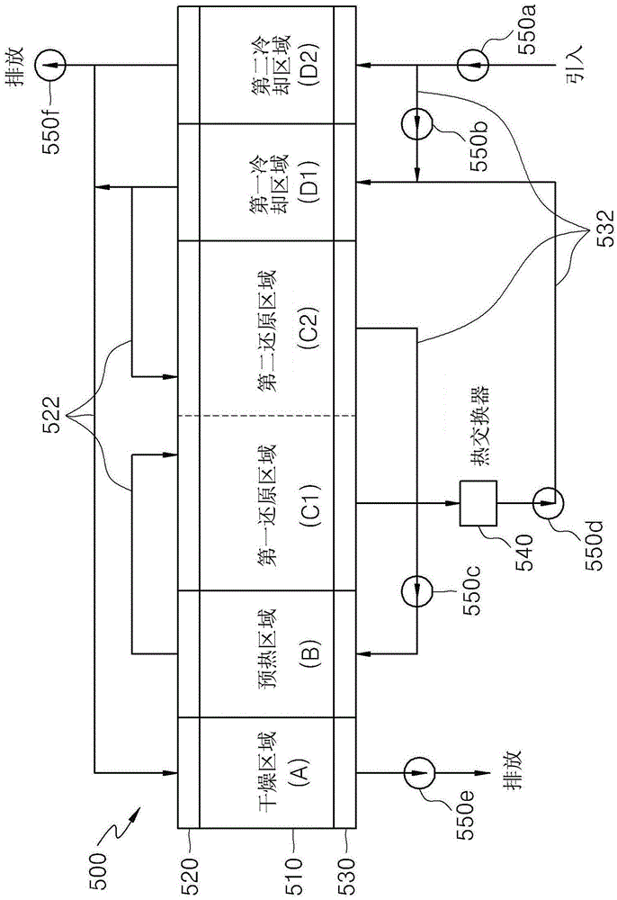
[0062] figure 2 is a block diagram showing the internal structure of the combustion apparatus and the flow of fluid according to the exemplary embodiment.

[0063] refer to figure 2 , the combustion equipment 500 includes: a combustion furnace 510 that defines a path that allows a trolley that accommodates coal blocks to move; an upper passage 520 that is provided in the upper part of the combustion furnace 510 to communicate with the The longitudinal direction is divided into a plurality of regions; the upper connecting pipe 522 is provided in the upper passage 520 to communicate with at least two different regions; the lower passage 530 is provided in the lower part of the combustion furnace 510 to communicate with the combustion furnace 510, and divided into a plurality of regions along the longitudinal direction of the combustion furnace 510; and a lower connection pipe 532 located on the lower passage 530 to communicate at least two different regions.

[0064] The fur...

example 2

[0093] Figure 5 is a schematic diagram showing the structure of a combustion device according to an exemplary embodiment, Image 6 It is a block diagram showing the internal structure of the combustion equipment and the fluid flow according to the movement of the coal block.

[0094] refer to Figure 5 with Image 6 , the combustion equipment 600 includes: a first combustion furnace 610, defining a linear path to heat the coal block, and a trolley accommodating the coal block therein moves from one side to the other side along the linear path; a second combustion furnace 620, defining an annular path to reduce the coal lumps, the annular path being connected to the other side of the first combustion furnace 610, the coal lumps discharged through the other side of the first combustion furnace 610 moving along the annular path; and The cooling area 630 connected to the second combustion furnace 620 defines an annular path to cool the reduced iron, the annular path is connect...


PUM


Abstract

The present invention relates to a burning apparatus and a method for manufacturing reduced iron using the same, and more particularly, to a burning apparatus heating a coal briquette to manufacture reduced iron, which includes a first burning furnace heating the coal briquette while moving the truck accommodating the coal briquette along a linear movement path; a second burning furnace connected to the other side of the first burning furnace, and heating the coal briquette while moving the coal briquette discharged from the truck along an annular path; and a cooling device connected to the second burning furnace, and cooling the reduced iron while moving reduced iron reduced in the second burning furnace along an annular path. The burning apparatus circulates exhaust gases generated in the burning furnace and cooling device to control a temperature and an oxygen concentration and thus improves a metallization rate of the reduced iron.

Description

technical field [0001] The present invention relates to combustion equipment and a method of producing reduced iron using the same, and more particularly, to a combustion equipment capable of increasing the metallization rate of reduced iron by controlling the temperature and oxygen concentration inside a combustion furnace and using the same A method of producing reduced iron. Background technique [0002] Typical reduced iron manufacturing equipment includes a plurality of hoppers accommodating iron raw materials and carbonaceous materials, respectively, a crusher that receives and crushes corresponding iron raw materials and carbonaceous materials, a mixer that receives and mixes iron raw materials and carbonaceous materials, A molding machine that compresses and shapes the resulting mixture obtained in the mixer and a combustion furnace that heat-treats and burns the briquettes (or briquettes) shaped in the molding machine. [0003] At the same time, coal lumps are heat...

Claims


Application Information

Patent Timeline
IPC IPC(8): C21B13/00F27B9/00F27B9/12F27D17/00
CPCC21B13/0066C21B13/0073C21B13/105C21B13/14F27B3/045F27B2017/0091F27D7/04F27D9/00F27D13/00F27D17/00F27D99/0033F27D99/007F27D2003/125Y02P10/134Y02P10/25
Inventor 孙相汉朴钟寅王敏奎黄炳云
Owner POHANG IRON & STEEL CO LTD
Why Eureka
Try Eureka