Centralized incineration equipment
A technology of equipment and incineration kiln, applied in the field of centralized incineration equipment, can solve the problems of production efficiency and cost impact, formation of smoke and dust, high impurity content, and achieve the effect of improving the burning effect, prolonging the service life and ensuring the burning effect.
- Summary
- Abstract
- Description
- Claims
- Application Information
AI Technical Summary
Problems solved by technology
Method used
Image
Examples
Embodiment 1
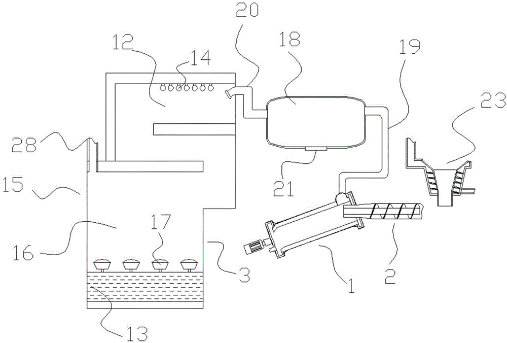
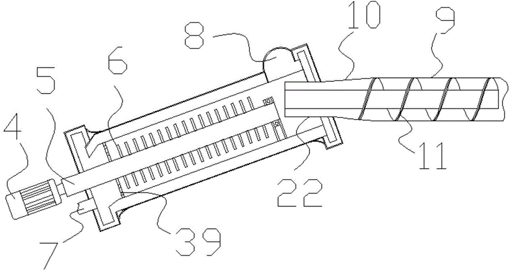
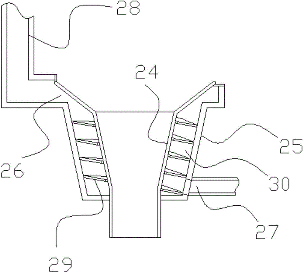
[0027] Embodiment 1: as figure 1 , figure 2 , image 3 , Figure 5 In the shown embodiment, a centralized incineration equipment includes an incineration kiln 1, a feeding device 2, a smoke cleaning device 3, and a material separation net: the incineration kiln has an incineration cavity, and the incineration kiln is inclined and parallel to the horizontal plane. Between 10 to 60 degrees, the incineration inner cavity is provided with a transmission spindle 5 driven by the main motor 4, and a plurality of bulk bodies 6 for moving materials are arranged on the transmission spindle. The incineration kiln is provided with an air inlet 7, a smoke outlet 8, and a feed port; the feeding device includes a feeding cylinder 9 and a compression portion 10, and the feeding auger 11 is arranged in the described feeding cylinder, and the described feeding device The compression part is connected between the feeding cylinder and the feed inlet, and the diameter of the compression part g...
Embodiment 2
[0037] Embodiment 2: the basic structure and implementation mode of this embodiment are the same as embodiment 1, and its difference is, as Figure 4 As shown, it also includes a cleaning motor, the transmission main shaft is provided with a main shaft inner cavity 31, and a transmission inner shaft 32 coaxial with the transmission main shaft extends into the main shaft inner cavity, and one end of the transmission inner shaft It is connected with the output shaft of the cleaning motor, and the other end is connected with the bearing of the inner shaft. The cleaning motor can also be arranged in the inner cavity of the main shaft. There are multiple cleaning devices on the transmission main shaft. The cleaning device Including a dirt ball 33, a limit ball 34, a ball receiving spring 35, a slide bar 36, and a slide hole arranged on the wall of the transmission main shaft, the slide bar is slidably matched with the slide hole, and the dirt ball and the limit ball The balls are r...
PUM
 Abstract
Description
Claims
Application Information
 - R&D
- Intellectual Property
- Life Sciences
- Materials
- Tech Scout
- Unparalleled Data Quality
- Higher Quality Content
- 60% Fewer Hallucinations
Browse by: Latest US Patents, China's latest patents, Technical Efficacy Thesaurus, Application Domain, Technology Topic, Popular Technical Reports.
© 2025 PatSnap. All rights reserved.Legal|Privacy policy|Modern Slavery Act Transparency Statement|Sitemap|About US| Contact US: help@patsnap.com


