Heat pump drying system

A technology of heat pump drying and heat pump, which is applied in the direction of drying, drying machine, progressive drying machine, etc., can solve the problems of large floor area, and achieve the effects of reducing operating costs, improving quality, and reducing energy consumption

Inactive Publication Date: 2015-05-06
DONGGUAN HOTWHEELS ENERGY TECH
View PDF7 Cites 11 Cited by
  • Summary
  • Abstract
  • Description
  • Claims
  • Application Information

AI Technical Summary

Problems solved by technology

For large-scale drying lines, due to the large footprint, how to make full use of limited land resources to achieve high-quality, low-energy drying is also a major problem to be solved

Method used


Image

  • Heat pump drying system
  • Heat pump drying system
  • Heat pump drying system

Examples


Embodiment Construction

[0021] The structure of the present invention will be described in detail below in conjunction with the accompanying drawings.

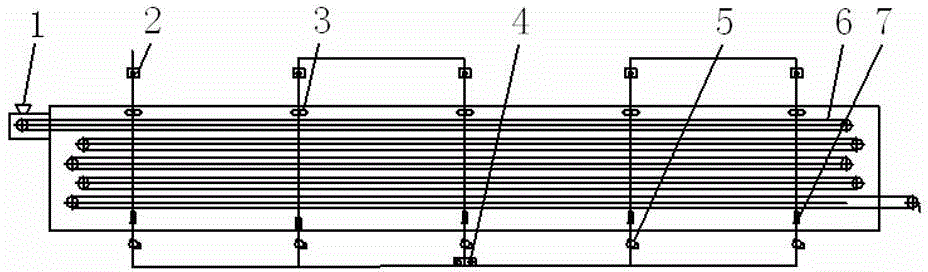
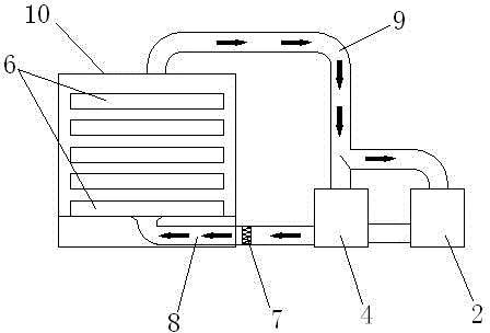
[0022] A heat pump drying system, comprising a plurality of drying chambers 10 connected in series, each drying chamber is provided with a transmission mesh belt 6 for conveying materials, the transmission mesh belt 6 is provided with mesh holes capable of ventilation, and the mesh The hole size should not be smaller than the material. The discharge end of the transmission mesh belt in the previous drying chamber is connected to the feed end of the transmission mesh belt in the next drying chamber by the feeding device 13 . Each drying chamber 10 is provided with an independently controlled hot air supply mechanism. The air outlet of the hot air supply mechanism is located below the drying chamber 10, and an exhaust mechanism for discharging humid air is also provided above the drying chamber.

[0023] The hot air supply mechanism is provided w...


PUM


Abstract

A heat pump drying system comprises a plurality of drying chambers which are sequentially connected in series, wherein a transmission net belt is arranged in each drying chamber, and the discharging end of the transmission net belt in the previous drying chamber is connected to the feeding end of the transmission net belt in the next drying chamber through a feeding device; a hot air supply mechanism which is independently controlled is arranged in each drying chamber, and an air exhaust mechanism is arranged above the drying chambers; each hot air supply mechanism is provided with a hot air channel and a heat pump, and the air exhaust mechanism is provided with an air exhaust channel which is connected with the hot air channels to form a gas circulation channel; an evaporator of each heat pump and the air exhaust channel form a heat exchange mechanism used for transmitting heat in humid and hot gas into heat pump mediums to achieve condensation dehumidification; a condenser of each heat pump and the corresponding hot air channel form a heat exchange mechanism used for transmitting heat in the heat pump mediums to airflow in the corresponding hot air channel to achieve heat circulation, heat circulation is achieved, and the energy utilization rate is effectively reduced.

Description

technical field [0001] The invention relates to a drying device, in particular to a heat pump drying system. Background technique [0002] In the fields of Chinese herbal medicine processing, food processing, and industrial product drying, drying equipment is required for drying. At present, most of the large-scale industrialized material drying lines still use the boiler heating method. Whether it is a gas-fired boiler or a coal-fired boiler, the energy utilization rate is not high, and the exhaust smoke of the boiler will also cause environmental pollution. Some of the air-energy drying equipment that has appeared are also miniaturized equipment, and the hot and humid air during the drying process is directly discharged. For large-scale drying lines, due to the large footprint, how to make full use of limited land resources to achieve high-quality, low-energy drying is also a major problem to be solved. Contents of the invention [0003] The technical probl...

Claims


Application Information

Patent Timeline
Patent Type & Authority Applications(China)
IPC IPC(8): F26B15/18F26B21/00
Inventor 王俊平吴涛
Owner DONGGUAN HOTWHEELS ENERGY TECH
Why Eureka
Try Eureka