
A Method to Solve Temperature Drift of Distributed Optical Fiber Raman Temperature Sensing System

A distributed optical fiber, sensing system technology, applied in thermometers, thermometers with physical/chemical changes, measuring devices, etc., can solve the problems of inability to exclude the influence of system stability, sacrificing system flexibility, poor dynamic response speed, etc. , to achieve the effect of low power consumption, improved temperature measurement accuracy, and fast dynamic response speed

Inactive Publication Date: 2017-07-11
JILIN UNIV
View PDF1 Cites 2 Cited by
  • Summary
  • Abstract
  • Description
  • Claims
  • Application Information

AI Technical Summary

Problems solved by technology

The application of the above technologies has played an important role in improving the stability of the distributed optical fiber Raman temperature sensing system, but the above technologies only compensate the temperature effect of each module within a limited range, and the performance of other devices in the system is still can be affected by temperature changes
In order to eliminate this effect from the system as a whole, the system can be placed in a controllable thermostat, but this increases the cost of the system, sacrifices the flexibility of the system, and for the application environment with rapid temperature changes, the dynamic response speed is poor , at the same time, it is impossible to rule out the influence of the small crosstalk of each component in the system on the stability of the system

Method used


Image

  • A Method to Solve Temperature Drift of Distributed Optical Fiber Raman Temperature Sensing System
  • A Method to Solve Temperature Drift of Distributed Optical Fiber Raman Temperature Sensing System
  • A Method to Solve Temperature Drift of Distributed Optical Fiber Raman Temperature Sensing System

Examples


Embodiment Construction

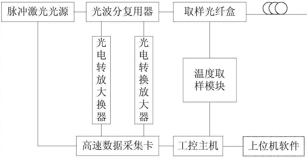
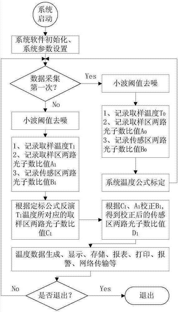
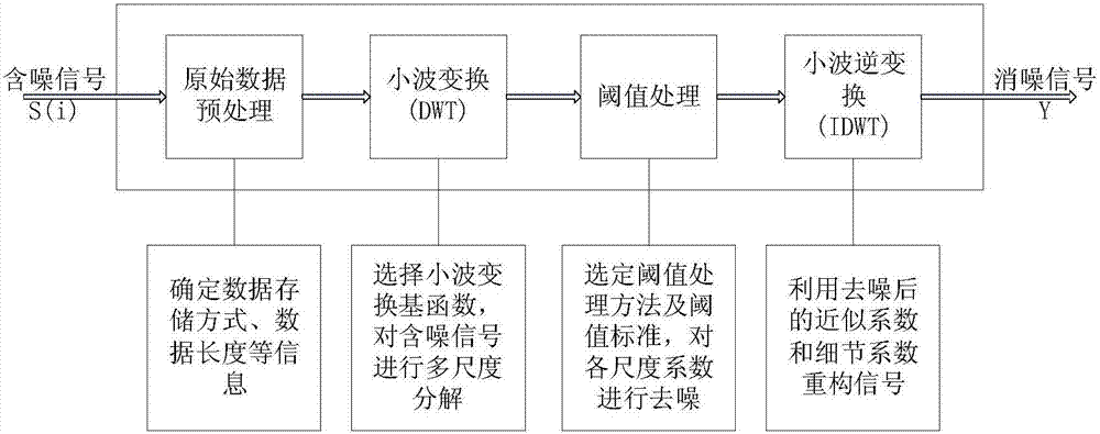
[0031] The specific implementation of a method for solving the temperature drift of a distributed optical fiber Raman temperature sensing system can be mainly divided into system device design, temperature demodulation formula calibration, implementation of dynamic sampling correction method, and signal denoising.

[0032] 1. System device design

[0033](1) The pulsed laser light source is driven by a high-speed pulse drive circuit, the output power of the light source is stabilized by the automatic power control circuit according to the LD back optical power value, and the LD operating temperature is maintained by the automatic temperature control circuit. The optical power and pulse width of the pulsed laser light source And the repetition frequency is adjustable, the adjustable range of the optical power is 0mW-10mW, the adjustable range of the pulse width is 5ns-1000ns, and the adjustable range of the repetition frequency is 1KHz-10KHz. The light is output through the iso...


PUM

PropertyMeasurementUnit
wavelengthaaaaaaaaaa

Abstract

A method to solve the temperature drift of the distributed optical fiber Raman temperature sensing system, its realization mainly depends on the design of the dynamic temperature sampling module, the development of the dynamic sampling correction method and the application of the wavelet analysis method. Using the temperature data in the sampling fiber box obtained by the temperature detection module and the reference data relative to the sampling fiber region and the sensing data relative to the sensing fiber region collected by the high-speed data acquisition card, using the dynamic sampling correction method proposed by the present invention, It can make the system work stably within the temperature range of -25°C to 45°C, and solve the problem of temperature drift caused by ambient temperature changes or small crosstalk between components in the system. The specific application of the wavelet analysis method effectively improves the temperature measurement accuracy of the system and ensures that the temperature measurement error of the system is within ±1°C.

Description

technical field [0001] The invention relates to a method for solving the temperature drift of a distributed optical fiber Raman temperature sensing system, in particular to a dynamic temperature sampling module and a dynamic sampling correction method that can make the system operate stably under ambient temperature changes from -25°C to 45°C Jointly developed and wavelet analysis methods in [0002] Specific application in distributed optical fiber Raman temperature sensing system. Background technique [0003] The distributed optical fiber Raman temperature sensing system (DTS) is based on the principle of spontaneous Raman scattering (Raman Scattering) to realize the measurement of the temperature of the area along the optical fiber. The optical fiber is not only a sensing medium for temperature information, but also a transmission medium for temperature information. , the use of optical time domain reflectometry (OTDR) technology can accurately determine the position of...

Claims


Application Information

Patent Timeline
Patent Type & Authority Patents(China)
IPC IPC(8): G01K11/32G01K11/324
Inventor 于淼常天英崔洪亮陈建冬刘野郎金鹏
Owner JILIN UNIV
Learn More