

Gas dissolving device
A technology of dissolving device and gas, which is applied in the directions of dissolving, dissolving, transportation and packaging, etc., can solve the problems of reducing dissolution efficiency and preventing micronization.
- Summary
- Abstract
- Description
- Claims
- Application Information
AI Technical Summary
Problems solved by technology
Method used
Image

Examples
Embodiment approach 1
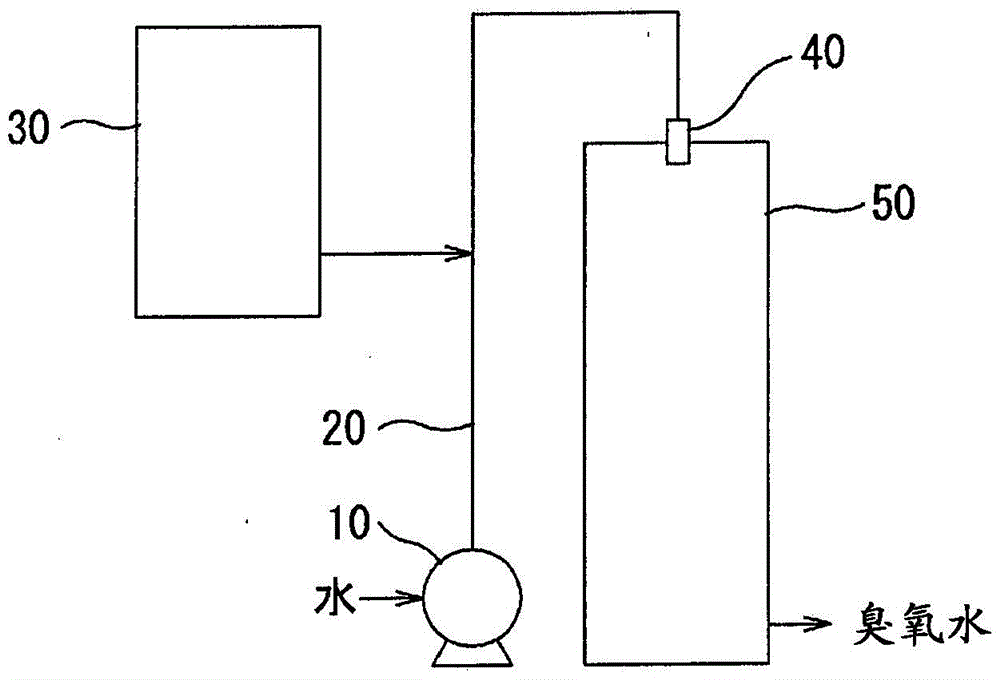
[0028] figure 1 It is a conceptual diagram which shows the whole structure of the gas dissolution apparatus which concerns on one Embodiment of this invention. figure 1 The gas dissolving device mixes ozone in water and dissolves it.
[0029] Water is pressurized by the pump 10 and flows through the piping 20 . In the middle of the pipe 20 , the ozone gas supplied from the ozone generator 30 is mixed, and the gas-liquid mixture is sprayed into the tank 50 from the nozzle 40 provided at the front end of the pipe 20 in a pressurized state. As will be described later, the gas-liquid mixture is stirred in the tank 50, and based on the stirring, the gas-liquid mixture (ozone water) in which ozone is dissolved to a supersaturated state is taken out from the lower part of the tank 50, and the ozone water taken out is treated in waste water. , water treatment, etc.
[0030] be explained, in figure 1 In the above embodiment, the pump 10, the piping 20, and the ozone generator 30 ar...
Embodiment approach 2
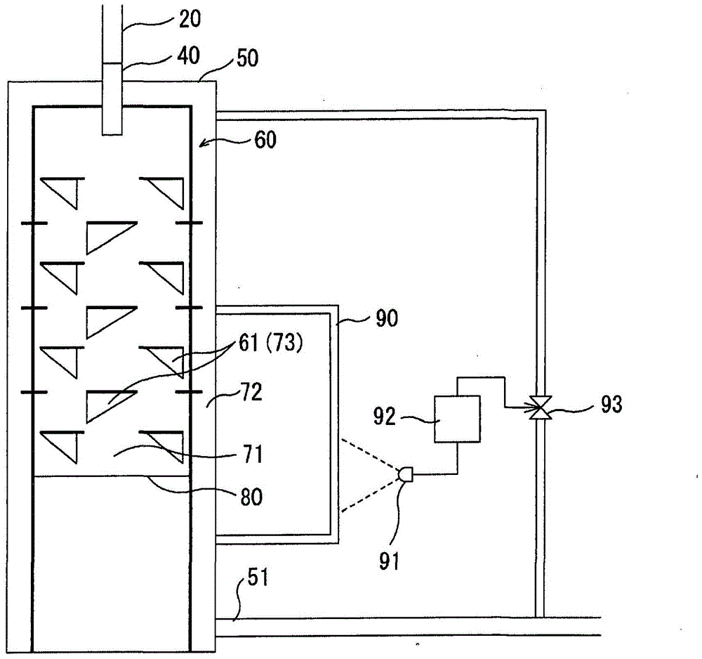
[0040] image 3 It is a cross-sectional view showing another embodiment of the tank of the gas dissolving device of the present invention. In this figure, the same reference numerals are assigned to the same configurations as in the previous first embodiment, and description thereof will be omitted.
[0041] In the present embodiment, a collision plate 80 that blocks the central flow path 71 is provided at the lower portion of the inner cylindrical body 60 disposed in the tank 50 . If the collision plate 80 is provided in this way, since the gas-liquid mixture passing through each flow path collides with the collision plate 80 and bounces back, the residence time can be increased, and the transfer of the micronized gas (ozone) to the liquid (water) can be further promoted. dissolve.
[0042] In addition, in this embodiment, the through-hole 61 is not provided in the inner cylinder 60 in the area below the collision plate 80 , but the through-hole 61 may be provided in the ar...
Embodiment approach 3
[0051] Figure 4 It is a sectional view which shows still another embodiment of the tank of the gas dissolving apparatus of this invention. In this figure, the same reference numerals are assigned to the same configurations as those in the previous Embodiments 1 and 2, and description thereof will be omitted.
[0052] In this embodiment, a plurality of annular bodies 100 are used to form a partition body provided in the tank 50 . That is, in the present embodiment, the division body is formed by the annular body 100 arranged in multiple stages at intervals in the longitudinal direction of the tank 50, the inner side of the annular body 100 is the central flow path 71, and the outer peripheral surface of the annular body 100 and the Outer flow paths 72 are formed between the inner peripheral surfaces of the tanks, and connecting flow paths 73 are formed between the annular bodies.
[0053] Also in this embodiment, as in the previous Embodiment 1, the gas-liquid mixture is eff...
PUM
 Abstract
Description
Claims
Application Information