A special machine for automatic lamp cap riveting

A technology of riveting point and special machine, which is applied to lamp head riveting machine. , In the field of riveting mechanism, it can solve problems such as large working error, low riveting efficiency, and unsuccessful riveting, and achieve the effects of reducing assembly and debugging time, improving work efficiency, and reducing power requirements

Inactive Publication Date: 2016-07-06
MAANSHAN LIANBANG INTELLIGENT EQUIP
View PDF9 Cites 0 Cited by
  • Summary
  • Abstract
  • Description
  • Claims
  • Application Information

AI Technical Summary

Problems solved by technology

[0008] In view of the poor synchronization of the cylinders in the existing technology, the working error is large, and some irregularities will lead to unsuccessful riveting and high defective products; the riveting of the cylinders is not performed synchronously, which will cause the riveting points to be punched in different depths, which is not easy Adjustment; the whole machine is huge and the cost is high; only one lamp cap can be riveted at a time, the transfer of the lamp cap in the assembly line is complicated, and the placement of the lamp cap needs to be completed manually or by a robot, and the riveting efficiency is low. The present invention provides an automatic lamp cap riveting point Special machine, it can achieve uniform depth of riveting points, reduce defective products, simplify the structure of the machine, and at the same time adapt to assembly line transmission to improve riveting efficiency

Method used


Image

  • A special machine for automatic lamp cap riveting
  • A special machine for automatic lamp cap riveting
  • A special machine for automatic lamp cap riveting

Examples


Embodiment 1

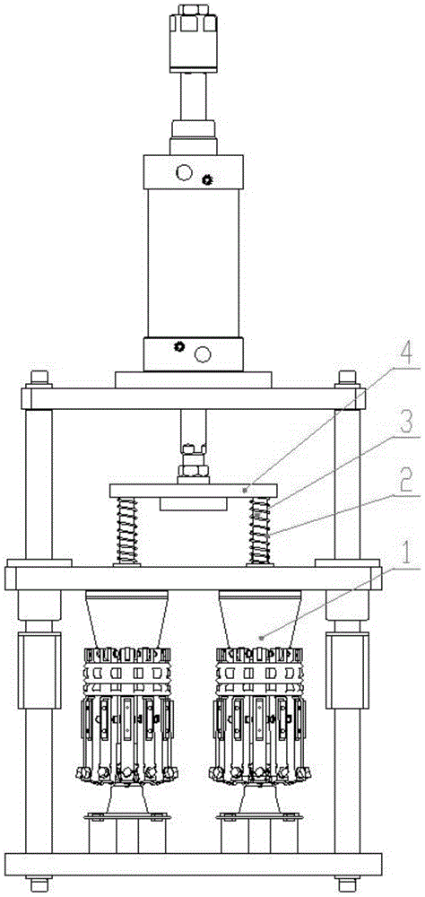
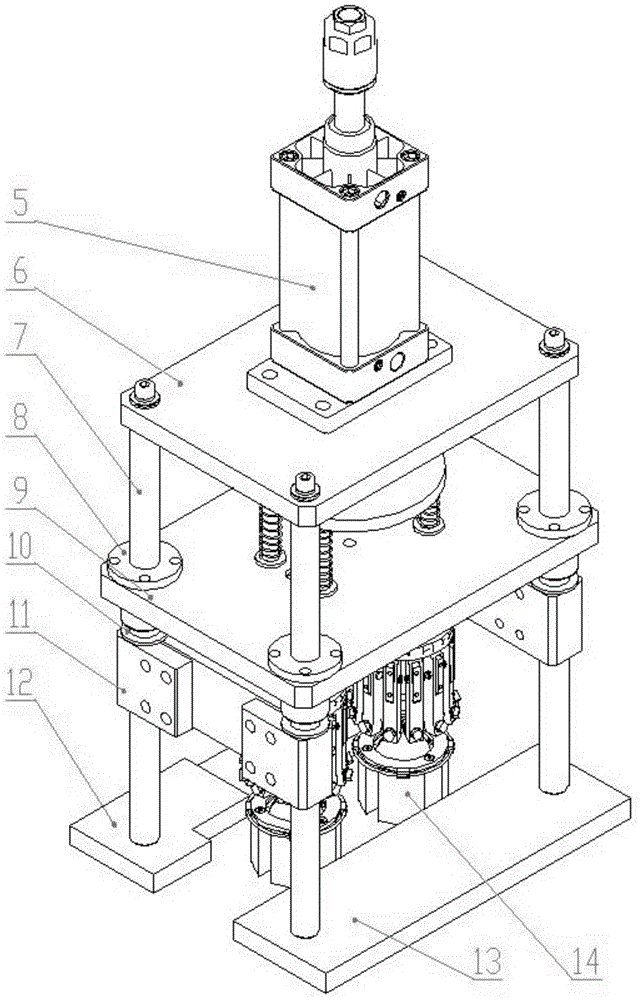
[0034] Such as figure 1 with figure 2 As shown, this embodiment is mainly composed of a riveting device 1, a compression spring 2, a connecting rod 3, a connecting plate 4, a cylinder 5, a top plate 6, a column 7, a linear bearing 8, a lifting plate 9, a rubber pad 10, and a limit splint 11 , Front base plate 12, rear base plate 13 are formed.

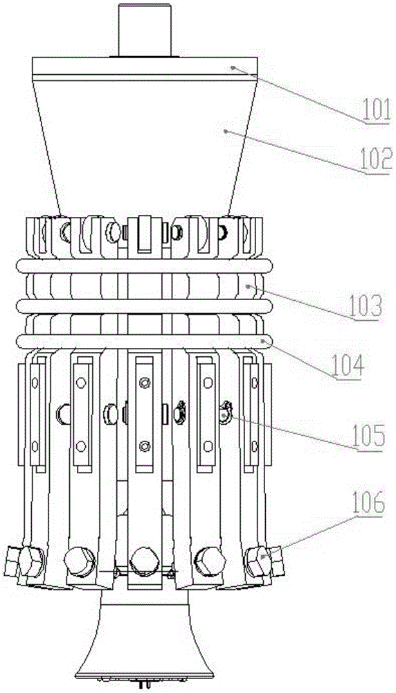
[0035] Such as image 3 with Figure 4 As shown, the pressure riveting device 1 is composed of a polyoxymethylene cover 101, a tapered platform 102, a strip lever 103, a small extension spring 104, a round pin 105, a riveting needle 106, a fixed shaft seat 107, a roller 108, a roller shaft 109, a small Square 110, little stage clip 111, stuffy cover 112, push post 113 form.

[0036] The polyoxymethylene sleeve 101 and the conical platform 102 are screwed together. The polyoxymethylene cover 101 is enclosed within the fixed shaft seat 107 top, and can slide up and down in its shaft. The fixed shaft seat 107 is fixed with a small ...


PUM


Abstract

The invention discloses a special and automatic lamp holder point riveting machine, belongs to the field of machining equipment, and relates to a lamp holder riveting machine. The special point riveting machine comprises a rivet pressing device, compression springs, connecting rods, a connecting disk, a cylinder, a top plate, stand columns, a lifting plate, limiting clamping plates, a front bottom plate and a rear bottom plate, wherein the rivet pressing device comprises a polyformaldehyde sleeve, a conical platform, long-strip-shaped levers, small tension springs, round pins, riveting needles, a fixing shaft base, small square blocks and a small compression spring, the polyformaldehyde sleeve and the conical platform are connected and arranged on the upper portion of the fixing shaft base in a sleeving mode, the round pins penetrate through the middles of the small square blocks fixed by the fixing shaft base, the long-strip-shaped levers are hung on the round pins, the riveting needles are fixed to the lower ends of the long-strip-shaped levers, the upper portions of the long-strip-shaped levers are sleeved with the small tension springs, the polyformaldehyde sleeve, the connecting rods and the connecting disk are fixedly connected with a cylinder piston, the compression springs penetrate through the middles of the connecting rods, and the fixing shaft base is fixed to the lifting plate. Through the special machine, riveting points are unified and uniform in depth, bad products are reduced, the structure of the machine is simplified, and meanwhile the machine adapts to assembly line conveying and improves riveting efficiency.

Description

technical field [0001] The invention belongs to the field of mechanical processing equipment, and relates to a riveting mechanism, in particular to a lamp cap riveting machine. Background technique [0002] Under the economic model dominated by the market economy, in order to adapt to the rapidly changing market requirements, new requirements are put forward for assembly automation. For automated high-speed mechanical assembly, it is necessary to conduct in-depth research on precision assembly technology to adapt to the challenges brought by the development of modern precision machinery to assembly technology. At the same time, it can also greatly increase the product yield and productivity, reduce the production cost of enterprises, and improve the competitiveness of enterprises, which is of great significance to the development of enterprises and industries. [0003] Riveting and welding are two well-known methods in the industry to connect multiple panels. Among them, ri...

Claims


Application Information

Patent Timeline
Patent Type & Authority Patents(China)
IPC IPC(8): B21D39/00
CPCB21D39/00
Inventor 苏山山倪明姚路路
Owner MAANSHAN LIANBANG INTELLIGENT EQUIP
Why Eureka
Try Eureka