Multifunctional conveying machine

A multifunctional conveying and conveyor technology, which is applied in the field of cargo loading and unloading conveying equipment and belt loading and unloading conveyors, can solve the problems of time-consuming and laborious, long preparation time, and single operation, so as to improve economic benefits, reduce loading and unloading operation costs, and reduce The effect of labor intensity

Active Publication Date: 2015-05-13
大连佳和彩板构件有限公司
View PDF6 Cites 15 Cited by
  • Summary
  • Abstract
  • Description
  • Claims
  • Application Information

AI Technical Summary

Problems solved by technology

[0002] At present, there are many loading and unloading equipment for bagged goods used in trains, ships, and automobile containers. The most efficient and safest is the movable belt telescopic loader, which is installed on the chassis of the counterweight truck through the turntable device. The main cantilever is driven to rotate, and the other end of the main cantilever is connected to the auxiliary cantilever through the turntable device. The two ends of the auxiliary cantilever are respectively connected to a retractable belt feeding conveyor and a discharge conveyor through a turntable device. Conveyor; the loading and unloading machine integrates vehicle chassis, hydraulic outriggers, feeding conveyor, unloading conveyor, intermediate conveyor, hydraulic system, and electric control system, and drives the vehicle chassis through the hydraulic system and electric control system. Walking, steering, braking and driving, horizontal extension and vertical height adjustment of hydraulic outriggers, deployment and retraction of loading conveyors and unloading conveyors, and position and attitude adjustments; can realize safe and efficient loading and unloading operations, but This kind of loading and unloading machine has a long preparation time in the early stage, and one posture can only perform a single operation of loading or unloading. Changing the operation form requires readjusting the posture of the loading and unloading machine, which is time-consuming and laborious.

Method used


Image

  • Multifunctional conveying machine
  • Multifunctional conveying machine
  • Multifunctional conveying machine

Examples


Embodiment Construction

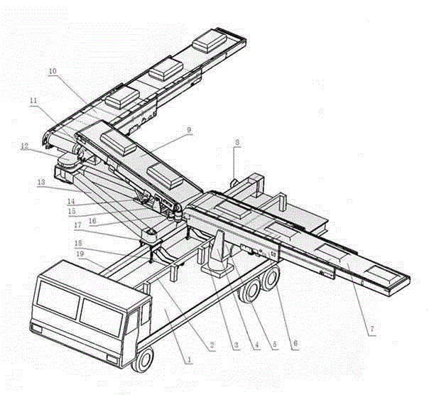
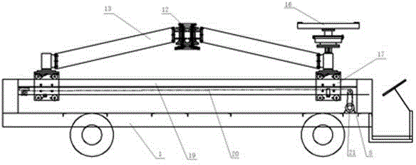
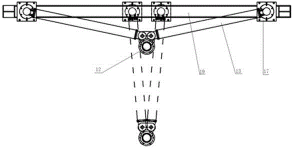
[0012] Embodiment is illustrated below in conjunction with accompanying drawing: select suitable vehicle chassis 1 with corresponding counterweight and hydraulic support leg for selection, and be equipped with hydraulic system, electronically controlled control system, be used to drive the walking, turning, braking and driving of vehicle chassis 1 Driving, lateral extension and vertical height adjustment of hydraulic outriggers, deployment and retraction of loading conveyor 7, discharge conveyor 10, intermediate conveyor 9, position and posture adjustment, loading conveyor 7, discharge conveyor 10 is a multi-stage telescopic conveyor belt; one end of the feeding conveyor 7 is connected to the turntable A5 through the support A4, and a hydraulic telescopic rod for adjusting its pitch angle is installed between the lower part of the support A4 and the first-stage conveying arm A6, and the turntable A5 is located at The chassis 1 is welded on the seat 3 on one side of the middle o...


PUM


Abstract

The invention provides a multifunctional conveying machine, and relates to railway freight transportation load and unload in the field of engineering machinery. The multifunctional conveying machine is composed of a vehicle chassis, a hydraulic supporting leg, a load and unload mechanism, a hydraulic system and an electronic control system. The hydraulic system and the electronic control system are adopted for driving the vehicle chassis to walk, turn, brake and drive, the hydraulic supporting leg to transversely stretch and longitudinally adjust a height ,and the load and unload mechanism to unfold, fold, locate, and adjust a posture. The multifunctional conveying machine is used to load and unload cargo in bag among a train, an automobile, a freight house and a railway platform, and has the advantages of reasonably using a load and unload device, being capable of saving the labor force and reducing the labor intensity of a work, improving the efficiency of loading, unloading and carrying, reducing the load and unload operation cost, being beneficial for the cargo integrity and operation safety, and the like.

Description

technical field [0001] The invention belongs to the technical field of mechanical manufacturing, and relates to a cargo loading and unloading conveying equipment, in particular to a movable, telescopic and steering belt loading and unloading conveyor. Background technique [0002] At present, there are many loading and unloading equipment for bagged goods used in trains, ships, and automobile containers. The most efficient and safest is the movable belt telescopic loader, which is installed on the chassis of the counterweight truck through the turntable device. The main cantilever is driven to rotate, and the other end of the main cantilever is connected to the auxiliary cantilever through the turntable device. The two ends of the auxiliary cantilever are respectively connected to a retractable belt feeding conveyor and a discharge conveyor through a turntable device. Conveyor; the loading and unloading machine integrates vehicle chassis, hydraulic outriggers, feeding convey...

Claims


Application Information

Patent Timeline
Patent Type & Authority Applications(China)
IPC IPC(8): B65G65/00B65G37/00
CPCB65G37/00B65G67/08B65G67/30B65G67/60
Inventor 付文甲
Owner 大连佳和彩板构件有限公司
Why Eureka
Try Eureka