Thermal infrared imaging measuring system and method for oil film on water surface

A technology of thermal infrared imaging and oil film on water surface, which is applied in measurement devices, optical radiation measurement, radiation pyrometry, etc., can solve the problems of affecting detection accuracy, complicated operation and high cost, and achieves rich information, small size, and accurate qualitative analysis. and quantitative measures of the effect

Inactive Publication Date: 2015-05-13
BEIJING RES CENT OF INTELLIGENT EQUIP FOR AGRI
View PDF5 Cites 8 Cited by
  • Summary
  • Abstract
  • Description
  • Claims
  • Application Information

AI Technical Summary

Problems solved by technology

[0007] The technical problem to be solved by the present invention is to solve the problems in the prior art such as complex operation, high cost and external factors affecting detection accuracy.

Method used


Image

  • Thermal infrared imaging measuring system and method for oil film on water surface
  • Thermal infrared imaging measuring system and method for oil film on water surface

Examples


Embodiment 1

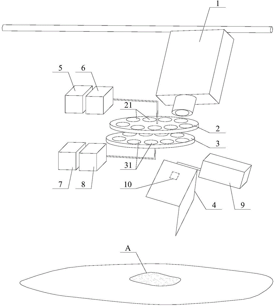
[0036] See figure 1 , which shows a schematic diagram of the overall structure of the thermal infrared imaging measurement system for the oil film on the water surface described in this embodiment. In this system, an infrared thermal imager 1 , a filter unit 2 , a polarizer unit 3 and a reflective galvanometer 4 are sequentially arranged along the thermal infrared information collection path.

[0037] Wherein, the infrared thermal imaging camera 1 is used to collect thermal infrared information of the current water surface, so as to obtain the qualitative measurement results of the type of oil slick and the quantitative measurement result of the thickness of the oil film. The detector of the thermal imaging camera 1 can be a focal plane uncooled detector with a pixel number of 320*256 and a wavelength of 8-14 μm. It is preferable to be able to adjust the focus electrically to improve operability. When measuring, hang the measuring system 80-120cm above the oil film A in the w...

Embodiment 2

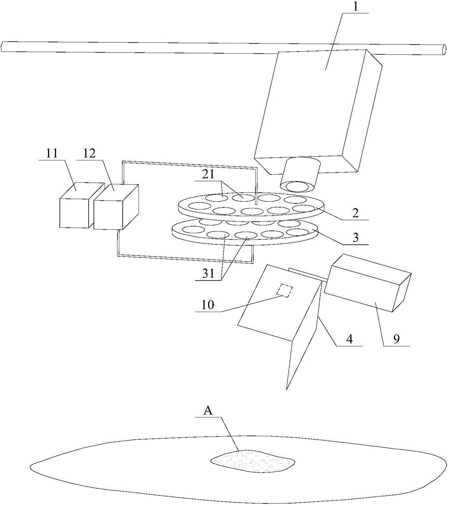
[0048] See figure 2 , which shows a schematic diagram of the overall structure of the thermal infrared imaging measurement system for the oil film on the water surface described in the second embodiment.

[0049] The difference between this program and the first embodiment is that the rotational driving force of the filter wheel and the polarizer wheel of the first embodiment is provided by the first driving device 5 and the second driving device 6 respectively; The rotational driving force of the optical film wheel and the polarizer wheel is provided by a driving device 11 , and the driving torque is output to the optical filter wheel and the polarizer wheel through the split speed reducer 12 .

[0050] Obviously, for the principle requirement of rotation speed, the rotation speed of the polarizer wheel is higher than that of the filter wheel. Other configurations and connection relationships of this solution are the same as those of the first embodiment, and will not be re...


PUM

PropertyMeasurementUnit
wavelengthaaaaaaaaaa

Abstract

The invention relates to the technical field of monitoring of floating oil, and in particular relates to thermal infrared imaging measuring system and method for an oil film on the water surface. The system comprises a thermal infrared imaging instrument, an optical filter unit, a polarizing film unit and a reflecting vibration mirror which are sequentially arranged; the thermal infrared imaging instrument is used for acquiring thermal infrared information of the current water source; the optical filter unit is equipped with a plurality of optical filters with different wave bands, and the plurality of optical filters can be adjusted to be respectively centered to a lens of the thermal infrared imaging instrument; the polarizing film unit is equipped with a plurality of polarizing films with different polarizing angles, and the plurality of polarizing films can be adjusted to be respectively centered to a lens of the thermal infrared imaging instrument; the reflecting vibration mirror is used for adjusting the working angle. Compared with the prior art, the system has the advantages that the interference of outside solar radiation, wind speed and other time and environmental factors on the measurement of the oil film on the water surface are avoided; the system is small in size, can quickly and accurately qualitatively and quantitatively measure the floating oil on the water surface, and is relatively high in operability, and controllable in manufacturing cost and use cost.

Description

technical field [0001] The invention relates to the technical field of oil slick monitoring, in particular to a thermal infrared imaging measurement system and method for an oil film on a water surface. Background technique [0002] With the application of oil in all aspects of social and economic life, oil pollution is also a major problem in contemporary environmental protection. Based on the fact that petroleum will not naturally degrade in a short period of time, if it is allowed to leak into the environment, it will cause major harm and impact on the environment and ecological balance. [0003] At present, the monitoring of oil slicks on the water surface has been highly valued by countries all over the world. The main monitoring methods include visible light remote sensing, laser fluorescence remote sensing, ultraviolet remote sensing, infrared remote sensing, microwave remote sensing and other remote sensing methods, which are divided into satellite remote sensing and...

Claims


Application Information

Patent Timeline
Patent Type & Authority Applications(China)
IPC IPC(8): G01J5/00G01N21/00G01B11/06
Inventor 郑文刚赵贤德董大明韩鹏程矫雷子郎筠郭瑞鲍锋
Owner BEIJING RES CENT OF INTELLIGENT EQUIP FOR AGRI
Why Eureka
Try Eureka