
Saw tooth structure plane waveguide visual optical display device for enhancing reality

A technology of optical display and planar waveguide, which is applied in the direction of optical components, optics, instruments, etc., can solve the problems of discomfort of the wearer, increased weight of the display system, and disadvantages, and achieve compact structure, reduced volume and weight, and low cost Effect

Active Publication Date: 2015-05-13
上海理湃光晶技术有限公司
View PDF6 Cites 38 Cited by
  • Summary
  • Abstract
  • Description
  • Claims
  • Application Information

AI Technical Summary

Problems solved by technology

For example, based on a 45° reflective structure display system, in order to increase the field of view, it can only be achieved by increasing the area of ​​the 45° reflective surface, which means that the weight of the overall display system increases, which brings discomfort to the wearer and is not conducive to lightness and flexibility. application of the system

Method used

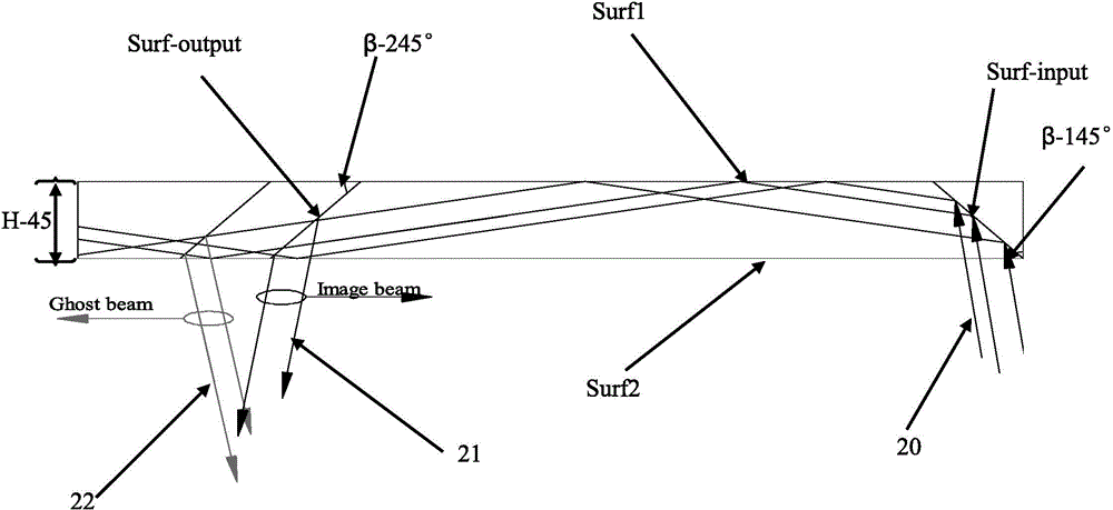
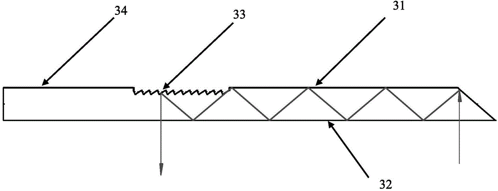

Image

  • Saw tooth structure plane waveguide visual optical display device for enhancing reality
  • Saw tooth structure plane waveguide visual optical display device for enhancing reality
  • Saw tooth structure plane waveguide visual optical display device for enhancing reality

Examples


Embodiment Construction

[0030] Below in conjunction with accompanying drawing, specific working process of the present invention is given description.

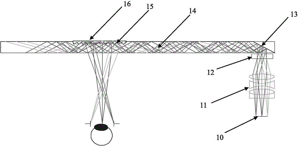
[0031] figure 1 It is a schematic diagram of the augmented reality sawtooth structure planar waveguide visual optical display device of the present invention. Such as figure 1 As shown, the system composition of the optical device of the present invention includes: an image display light source 10, a collimating lens group 11, a longitudinal expansion structure 12, a coupling reflection surface 13, a planar waveguide substrate 14, a sawtooth groove structure 15, and a prism-eliminating cover sheet 16 . The image shows that the light wave emitted by the light source 10 is collimated by the collimator lens group 11 and then enters the longitudinally expanded structure 12. The longitudinally expanded light wave passing through the longitudinally expanded structure is coupled into the coupling reflection surface 13, and enters the plane through the ref...


PUM


Abstract

The invention provides a saw tooth structure plane waveguide visual optical display device for enhancing reality. The saw tooth structure plane waveguide visual optical display device for enhancing the reality comprises an image display light source, a collimating lens group, a lengthways expansion structure, a coupling reflection plane, a plane waveguide substrate, a saw tooth grove structure and a prism effect elimination cover piece, wherein the image display light source sends out needed display light waves, the collimating lens group collimates light source light waves, the lengthways expansion structure expands a view field in the vertical direction, the coupling reflection plane couples the light waves after being expanded into the plane waveguide substrate, the plane waveguide substrate transmits the light waves which are coupled into the plane waveguide substrate in total reflection mode, a saw tooth structure is used for view field expansion in the horizontal direction and coupling output of the light waves, and the cover piece is used to eliminate ghost shadows and improve definition of an image. The saw tooth structure plane waveguide visual optical display device for enhancing the reality has the advantages of easily expanding a horizontal view field and the vertical view field, and being light and thin in waveguide, compact in structure, simple in processing technology and low in cost, and not only can be worn for display, but also can be used in fields of scene training simulation, medical ear mirrors, naked eye 3D (three dimensional) display, mobile display and the like.

Description

technical field [0001] The invention relates to a planar waveguide optical display device, in particular to a sawtooth structure planar waveguide visual optical display device with a large field of view, a compact structure and augmented reality. Background technique [0002] For wearable optical display components applied to augmented reality, in order to facilitate the wearer to obtain all information from the display light source in a timely manner, the display system is usually required to have a large field of view, light weight, small size and augmented reality effects. Traditional helmet-mounted displays are implemented based on 45° reflective structures or off-axis optical structures. These structures present a great contradiction in terms of increased field of view and overall weight of the helmet. For example, based on a 45° reflective structure display system, in order to increase the field of view, it can only be achieved by increasing the area of ​​the 45° refl...

Claims


Application Information

Patent Timeline
IPC IPC(8): G02B27/01
CPCG02B27/0101G02B2027/0123G02B2027/0178
Inventor 张圣军张庆
Owner 上海理湃光晶技术有限公司
Learn More