Rapid defogging method for road image

An image and road technology, which is applied in the field of rapid defog for road images, and can solve problems such as the defog effect is unfavorable for safe driving of vehicles

Active Publication Date: 2015-05-13
CENT SOUTH UNIV
View PDF15 Cites 15 Cited by
  • Summary
  • Abstract
  • Description
  • Claims
  • Application Information

AI Technical Summary

Problems solved by technology

[0005] The image defogging methods in the above documents and patents all use the method of uniformly enhancing the entire image. If these methods are directly applied to the foggy road image processing, it may be necessary to highlight distant scene objects. The nearby area is over-enhanced, and the defogging effect is not conducive to the safe driving of the vehicle.

Method used


Image

  • Rapid defogging method for road image
  • Rapid defogging method for road image
  • Rapid defogging method for road image

Examples


Embodiment 1

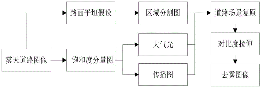
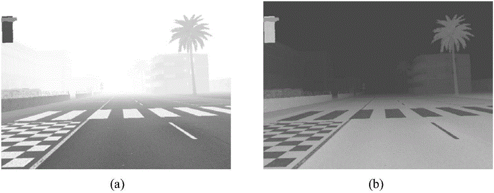
[0061] This embodiment is aimed at virtual fog road image Figure 4 (a) (size 640×480), according to figure 1 As shown, the defogging process is carried out in the following three steps:

[0062] 1. Calculate the atmospheric light value and propagation map through the saturation component of the original foggy road image;

[0063] The specific steps to implement this process include:

[0064] First, convert this virtual foggy road image from RGB color space to HSV color space, and extract its saturation component image.

[0065] Then, use the saturation component to obtain the dark primary color image D(I) of the original fog image. On this basis, the dark primary color image is arranged in descending order, and the positions of the points whose value is the first 1% in the dark primary color image are determined, and these positions correspond to the maximum pixel value in the original fog image area , which is the atmospheric light value A. The value of A in this exampl...

Embodiment 2

[0086] For actual foggy road images Figure 5 (a) (size is 800×600) for defogging. will first Figure 5 (a) Transform from RGB space to HSV space, and then obtain the dark primary color image of the original foggy image through the extracted saturation component. On this basis, obtain the atmospheric light A and the propagation map t. A value in the present embodiment is 0.9137.

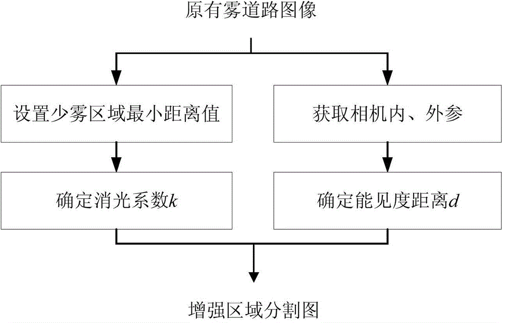
[0087] Then, use formula (2) to obtain the enhanced region segmentation map of the original foggy road image, where d min = 40, v h =210, σ=2610. Substitute this region segmentation map into formula (5) to obtain the restored image R, where the image adjustment factor w=0.6028.

[0088] Finally, use formula (6) to perform adaptive contrast stretching on the restored image to obtain the final dehazed road image Rf. where the two parameters of the formula V low and V high The values ​​were found to be 77 and 201, respectively.

Embodiment 3

[0090] For actual foggy road images Figure 6 (a) (size is 400×300) for dehazing treatment. will first Figure 6 (a) Transform from RGB space to HSV space, and then obtain the dark primary color image of the original foggy image through the extracted saturation component. On this basis, obtain the atmospheric light A and the propagation map t. The value of A in this embodiment is 1.

[0091] Then, use formula (2) to obtain the enhanced region segmentation map of the original foggy road image, where d min = 40, v h =105, σ=2610. Substitute this region segmentation map into formula (5) to obtain the restored image R, where the image adjustment factor w=0.6730.

[0092] Finally, use formula (6) to perform adaptive contrast stretching on the restored image to obtain the final dehazed road image Rf. where the two parameters of the formula V low and V high The values ​​were found to be 23 and 216, respectively.

[0093] Figure 4 , Figure 5 and Figure 6 It shows the c...


PUM


Abstract

The invention discloses a rapid defogging method for a road image. The rapid defogging method for the road image includes: step 1, obtaining an atmosphere light value and a propagation diagram according to a saturation component of the initial fog weather road image; step 2, obtaining an enhancement region segmentation diagram according to a visibility expression, and restoring the initial fog weather road image; step 3, performing contrast stretching treatment on the restored image so as to confirm the road image after being defogged. The rapid defogging method for the road image is established based on road scene image characteristics, different from a unified enhancement mode for the whole image in most existing defogging methods due to the fact that the rapid defogging method for the road image uses weak enhancement to process an area of the image, close to the ground, and simultaneously uses a mode of focusing on enhancing a far area where a driver is interested, and thereby achieves efficient and rapid defogging treatment for the fog weather road image, and can be widely used in fields of a safety driving assist system, autonomous car driving and the like. Additionally, the rapid defogging method for the road image is low in space-time complexity and high in working speed.

Description

technical field [0001] The invention belongs to the field of image information processing, and in particular relates to a fast defogging method for road images. Background technique [0002] One of the main causes of frequent traffic accidents is the reduced visibility due to bad weather, especially foggy days. Under such severe weather conditions, road images captured by on-board cameras are often seriously degraded, which makes current in-vehicle applications that rely on sensors such as cameras very sensitive to weather conditions. Therefore, the vehicle-mounted vision system should take the adverse effects of fog into account to improve the reliability of the system, which requires us to study a new algorithm that can effectively improve the visibility and contrast of foggy road images in real time. Various vision-based vehicle safety assisted driving systems are of great significance. [0003] At present, most of the existing image defogging algorithms, whether they a...

Claims


Application Information

Patent Timeline
Patent Type & Authority Applications(China)
IPC IPC(8): G06T5/00
Inventor 郭璠唐琎彭辉邹北骥
Owner CENT SOUTH UNIV
Why Eureka
Try Eureka