Multi-level converter submodule as well as inverter circuit and MMC topology both manufactured from such submodule
A multi-level converter and sub-module technology, which is applied in the directions of irreversible DC power input conversion to AC power output, high-efficiency power electronic conversion, and AC power input conversion to DC power output, etc. The problem of large switching loss and high voltage can achieve the effect of reducing the output harmonic component, reducing the switching loss and increasing the switching frequency
- Summary
- Abstract
- Description
- Claims
- Application Information
AI Technical Summary
Problems solved by technology
Method used
Image

Examples
Embodiment 1
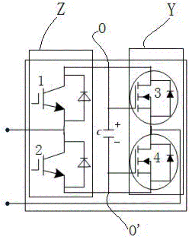
[0025] see image 3 The multilevel converter sub-module shown uses IGBT and S i C-MOSFET hybrid full-bridge sub-module structure design, including left branch Z, right branch Y, capacitor C, left branch Z, right branch Y, and capacitor C are connected in parallel, and left branch Z includes 2 IGBTs Components, the first IGBT element 1 and the second IGBT element 2, the right branch Y includes 2 S i C-MOSFET components, the first S i C-MOSFET element 3 and the second S i C-MOSFET element 4, the first IGBT element 1, the second IGBT element 2, the first SiC-MOSFET element 3 and the second SiC-MOSFET element 4 are bridged in sequence, that is, the emitter of the first IGBT element 1 is connected to the second IGBT The collector of element 2, the emitter of the second IGBT element 2 is connected to the source of the second SiC-MOSFET element 4, the drain of the second SiC-MOSFET element 4 is connected to the source of the first SiC-MOSFET element 3, the first The drain of the ...
Embodiment 2
[0029] see Figure 4 Shown: The inverter circuit made of multi-level converter sub-module, using IGBT and S i C-MOSFET hybrid full-bridge sub-module structure design, including left branch Z, right branch Y, capacitor C, resistor R and reactor G, left branch Z, right branch Y, capacitor C are connected in parallel, left Branch Z includes 2 IGBT elements, the first IGBT element 1 and the second IGBT element 2, and the right branch Y includes 2 S i C-MOSFET components, the first S i C-MOSFET element 3 and the second S i C-MOSFET element 4, the first IGBT element 1, the second IGBT element 2, the first SiC-MOSFET element 3 and the second SiC-MOSFET element 4 are bridged in sequence, that is, the emitter of the first IGBT element 1 is connected to the second IGBT The collector of element 2, the emitter of the second IGBT element 2 is connected to the source of the second SiC-MOSFET element 4, the drain of the second SiC-MOSFET element 4 is connected to the source of the first S...
Embodiment 3
[0032] Such as Figure 5 As shown, the MMC topology made of multi-level converter sub-modules is composed of six bridge arms 5, and each bridge arm 5 is composed of several interconnected multi-level converter sub-modules SM and a reactor L series structure, the upper and lower bridge arms form a phase unit, the six bridge arms are symmetrical, and the electrical parameters of each sub-module and the reactance value of each bridge arm are the same. The structure of the multilevel converter sub-module SM is as follows image 3 As shown, the structure adopts a three-phase six-branch structure, each bridge arm 5 is formed by cascading a certain number of quantum modules, and a reactor L is configured to suppress the circulating current and the rate of rise of the fault current. by IGBT with S i The multi-level converter sub-module composed of C-MOSFET mix can be regarded as a small power converter, and the improvement of the switching frequency of each unit will definitely make...
PUM
 Abstract
Description
Claims
Application Information
 - Generate Ideas
- Intellectual Property
- Life Sciences
- Materials
- Tech Scout
- Unparalleled Data Quality
- Higher Quality Content
- 60% Fewer Hallucinations
Browse by: Latest US Patents, China's latest patents, Technical Efficacy Thesaurus, Application Domain, Technology Topic, Popular Technical Reports.
© 2025 PatSnap. All rights reserved.Legal|Privacy policy|Modern Slavery Act Transparency Statement|Sitemap|About US| Contact US: help@patsnap.com