Two-dimensional ultrasound vibration platform

A two-dimensional ultrasonic vibration and platform technology, which is applied in the direction of fluid, solid separation, and filter screens using vibration, can solve the problems of large spindle changes and poor transplantability

Inactive Publication Date: 2015-05-20
TIANJIN UNIV
View PDF4 Cites 33 Cited by
  • Summary
  • Abstract
  • Description
  • Claims
  • Application Information

AI Technical Summary

Problems solved by technology

This method has a large change to

Method used


Image

  • Two-dimensional ultrasound vibration platform
  • Two-dimensional ultrasound vibration platform
  • Two-dimensional ultrasound vibration platform

Examples


Embodiment Construction

[0019] In order to further understand the invention content, characteristics and effects of the present invention, the following examples are given, and detailed descriptions are as follows in conjunction with the accompanying drawings:

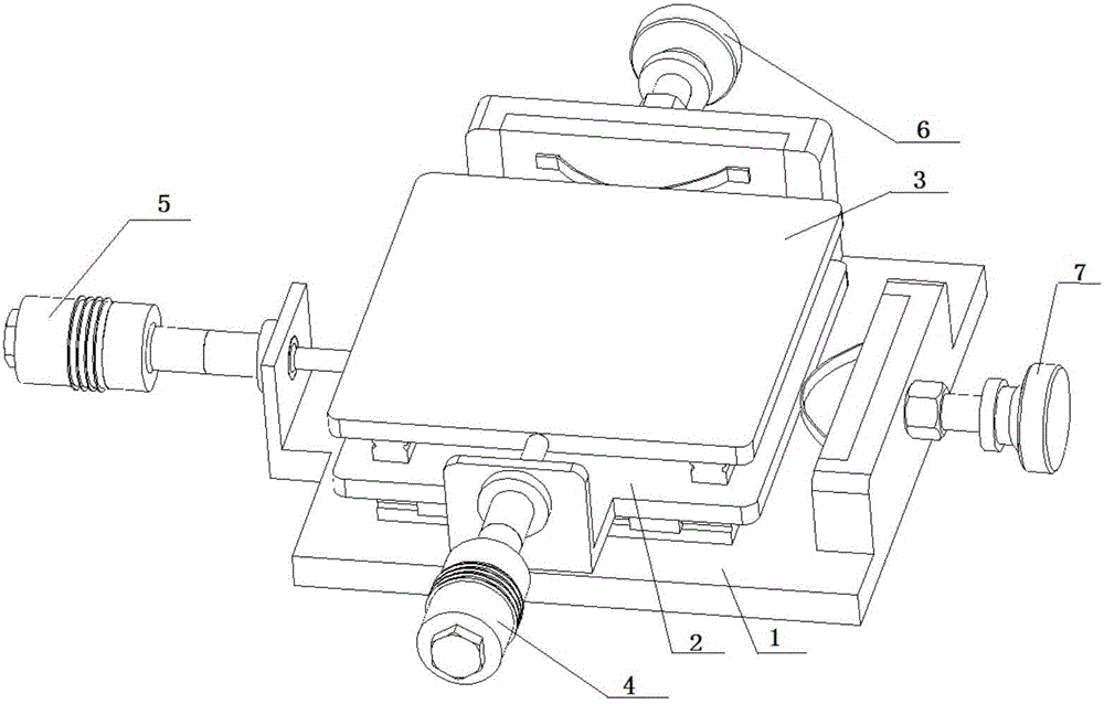
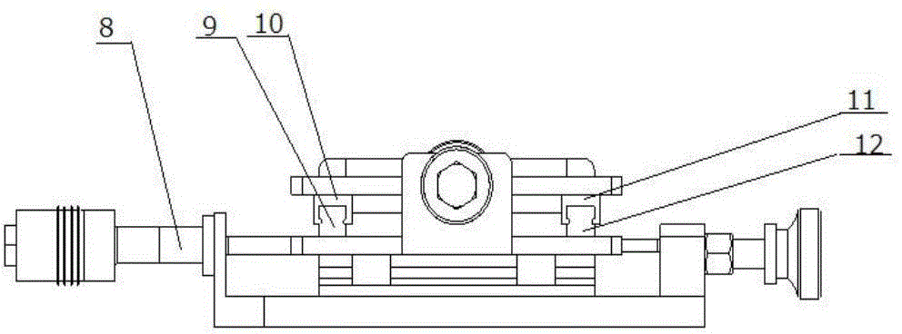
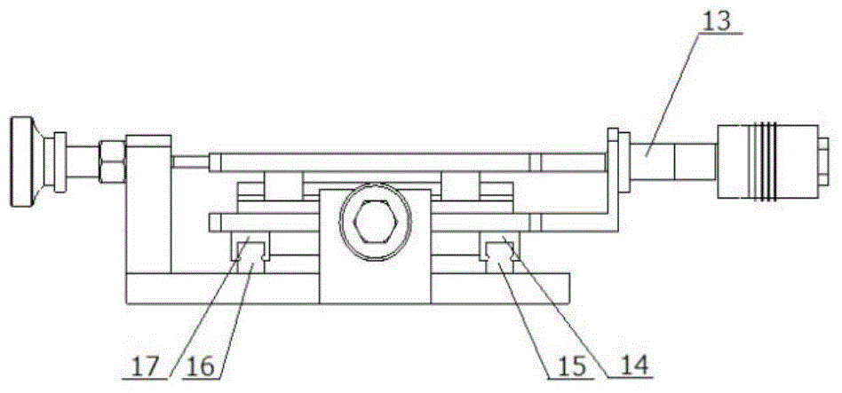
[0020] see Figure 1 to Figure 6 , a two-dimensional ultrasonic vibration platform, including a bearing plate 1, a lower vibration plate 2 and an upper vibration plate 3 arranged in sequence from bottom to top.

[0021] The lower vibrating plate 2 is connected to the bearing plate 1 through the X-direction linear motion guide rail; in this embodiment, there are two X-direction linear motion guide rails, one is composed of an X-direction track 15 and a slider 14, and the other is composed of an X-direction linear motion guide rail. X direction track 16 and slide block 17 are formed.

[0022] In the X direction, an X-direction vibrator is connected to one side of the lower vibrating plate 2, and an X-direction arched spring piece 19 is provide...


PUM


Abstract

The invention discloses a two-dimensional ultrasound vibration platform and relates to the technical field of non-traditional machining. The two-dimensional ultrasound vibration platform aims at solving the problems that cutting force is large and a tool is worn badly when a common micro milling machine is used for machining hard and brittle materials. The two-dimensional ultrasound vibration platform comprises a bearing plate, an upper vibrating plate, a lower vibrating plate, linear moving guide rails, bow spring pieces, fine adjusting devices, an ultrasonic power supply, ultrasonic amplitude transformers and ultrasonic transducers. The bottom of the bearing plate is directly fixed to a platform of a machine tool through bolts. The lower vibrating plate is mounted on the bearing plate. The middle of one side of the upper vibrating plate and the middle of one side of the lower vibrating plate are each connected with a vibrator. The bow spring pieces are arranged in the middles of the other sides of the vibrating plates. The two ends of each bow spring piece are fixed to the output end of the corresponding fine adjusting device. The amplitude transformers and the transducers are connected through threads to form the vibrators. According to the two-dimensional ultrasound vibration platform, the vibrators produce ultrasonic vibration to drive the upper vibrating plate and the lower vibrating plate to vibrate, different motion tracks can be coupled out according to different demands, and the two-dimensional ultrasound vibration platform is high in transportability and suitable for being popularized in vibration milling or other vibration screening fields.

Description

technical field [0001] The invention relates to the technical field of special processing, in particular to a two-dimensional ultrasonic vibration milling workbench. Background technique [0002] At present, some brittle and hard materials such as ceramics, silicon, diamond and optical glass are more and more widely used in aerospace, aviation, automobile, metallurgy, mechanical processing and other fields. Milling of such materials still has serious tool wear and development. High heat, low processing efficiency, etc., so it is imperative to explore a method that can take advantage of the advantages of milling and process hard and brittle materials. A feasible method to solve the above problems is to add ultrasonic vibration to the micro-milling machine. [0003] Ultrasonic machining is divided into traditional ultrasonic machining and ultrasonic-assisted machining. Traditional ultrasonic machining is to process the workpiece surface through the hammering, abrasion and tea...

Claims


Application Information

Patent Timeline
IPC IPC(8): B06B1/06B06B3/02B28D7/00B07B1/40
Inventor 袁言杰景秀并方浩文张大卫王福军
Owner TIANJIN UNIV
Why Eureka
Try Eureka