
Copper sheet flow guiding welding design and welding method for battery copper top cover

A technology of copper sheet and top cover, which is applied in the direction of welding equipment, resistance welding equipment, welding/welding/cutting items, etc. It can solve the problems that the welding current and time cannot be adjusted through electronic control, poor conductivity, and virtual welding, etc., to achieve The effect of saving procurement costs, improving production efficiency, and improving product quality

Active Publication Date: 2015-05-20
HEFEI GUOXUAN HIGH TECH POWER ENERGY
View PDF7 Cites 3 Cited by
  • Summary
  • Abstract
  • Description
  • Claims
  • Application Information

AI Technical Summary

Problems solved by technology

[0003] Since the energy stored in the capacitor needs to be released to the welding circuit at one time, the output energy adjustment is completed by controlling the charging energy of the capacitor. The output current is a pulse current, and the welding current and time cannot be adjusted by electronic control, so the welding is unstable. The chip needs to be brushed with solder paste and other flux to solder, and there will be false soldering
[0004] In the energy storage direct current resistance welding method adopted above, since the upper layer copper sheet has good conductivity, but the lower layer copper top cover has poor conductivity, the current basically flows from electrode-copper sheet-electrode during welding, and it is difficult to flow through the lower layer copper top cover, resulting in The heat only acts on the surface of the copper sheet, so the copper sheet and the copper top cover cannot form a nugget, and the welding process is unstable. It is necessary to brush solder paste and other fluxes to assist welding, and there will be false welding.

Method used


Image

  • Copper sheet flow guiding welding design and welding method for battery copper top cover

Examples


Embodiment Construction

[0017] The embodiments of the present invention are described in detail below with reference to the accompanying drawings, but the present invention can be implemented in many different ways as defined and covered by the claims.

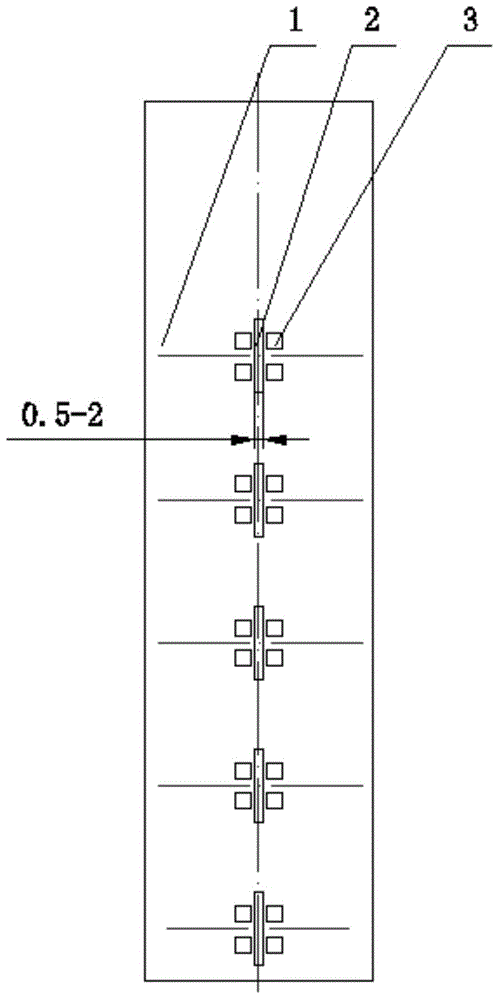
[0018] like figure 1 As shown in the figure, the present invention discloses a diversion welding design of a copper sheet. A diversion groove 2 is added at the welding position of the copper sheet 1. The width of the diversion groove 2 is 0.5-2 mm, and the diversion groove 2 is arranged on the Welding center position.

[0019] A method for welding a copper sheet and a copper top cover of a battery adopts intermediate frequency inverter direct current resistance welding, comprising the following welding steps:

[0020] (1) Adjust the welding parameters, adjust the intermediate frequency inverter DC spot welding machine to the appropriate welding parameters according to the specific equipment conditions and material requirements, set the welding curre...


PUM

PropertyMeasurementUnit
Widthaaaaaaaaaa

Abstract

The invention discloses copper sheet flow guiding welding design and a welding method for a battery copper top cover. A flow guiding groove is added in the welding position of a copper sheet, a loop can be formed by current between the copper top cover below and an electrode, intermediate-frequency inversion direct-current resistance welding is adopted, it is ensured that a molten core can be formed by the copper sheet and the copper top cover, and the welding process is stable. According to the copper sheet flow guiding welding design and the welding method for the battery copper top cover, it can be ensured that the copper sheet can be directly welded to the battery copper top cover, soldering flux such as soldering paste does not need to be brushed for auxiliary welding, pseudo soldering does not happen, soldering paste brushing personnel are reduced, the production efficiency is improved, pseudo soldering is avoided, the product quality is improved, and the soldering paste purchasing cost is saved.

Description

technical field [0001] The invention relates to the field of resistance welding of lithium ion batteries, in particular to a copper sheet inflow welding design and a welding method for a copper top cover of a battery. Background technique [0002] At present, the resistance welding method used for the copper sheet and the battery copper top cover is generally energy storage DC resistance welding, and its performance is as follows: [0003] Since the energy stored in the capacitor needs to be released to the welding circuit at one time, the output energy adjustment is completed by controlling the charging energy of the capacitor. The output current is pulse current, and the welding current and time cannot be adjusted by electronic control, so the welding is unstable and the copper The chip needs to be brushed with flux such as solder paste to be soldered, and false soldering occurs. [0004] In the above-mentioned energy storage DC resistance welding method, due to the good ...

Claims


Application Information

Patent Timeline
IPC IPC(8): B23K11/34B23K11/11
CPCB23K11/11B23K11/36B23K2101/36B23K2103/12
Inventor 徐光银宋金保韩成祥
Owner HEFEI GUOXUAN HIGH TECH POWER ENERGY
Learn More