
Junction temperature simulation circuit for semiconductor power devices

A technology for simulating circuits and power devices, used in instruments, thermometers and thermometers with electrical/magnetic components directly sensitive to heat, etc. Temperature protection power devices are difficult to apply safely, to achieve the effect of improving the safety and reliability of use

Active Publication Date: 2015-05-20
BEIJING HUAFENG TEST & CONTROL TECH CO LTD +1
View PDF3 Cites 4 Cited by
  • Summary
  • Abstract
  • Description
  • Claims
  • Application Information

AI Technical Summary

Problems solved by technology

[0003] 1. The temperature of the casing or heat sink is lower than the junction temperature (chip temperature) of the power device, and the temperature difference between the two is not a fixed value (depending on the power), and the temperature of the casing or heat sink is used as the safety protection of the power device The basis is not scientific
[0004] 2. In the pulse working mode, the temperature rise of the power device shell or heat sink lags behind the junction temperature rise of the power device. Under high-power pulses, the temperature of the heat sink is often not high, but the junction temperature of the power device has already exceeded the specified momentarily. The maximum junction temperature, which will cause damage to power devices
[0005] Therefore, only by obtaining the junction temperature of power devices in real time can it be possible to effectively protect the safe operation of power devices, but this is almost impossible for most power devices that do not have internal temperature measurement functions, so the real-time measurement of power device junction temperature And over-temperature protection has become a difficult problem for the safe application of power devices

Method used


Image

  • Junction temperature simulation circuit for semiconductor power devices
  • Junction temperature simulation circuit for semiconductor power devices
  • Junction temperature simulation circuit for semiconductor power devices

Examples


Embodiment Construction

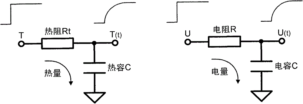
[0014] figure 1 The basic thermal model in can be expressed as:

[0015] q = λA δ ( T 1 - T 2 ) - - - ( 1 )

[0016] Formula (1) is the basic formula for heat conduction, where:

[0017] q is the heat that flows through the heat conductor per unit time;

[0018] λ is the thermal conductivity of the heat conductor;

[0019] A is the heat conduction cross-sectional area of ​​the heat conductor;

[0020] δ is the length along the direction of heat conduction in the heat conductor;

[0021] T1 and T2 are the temperatures of the two end sections of the heat conductor.

[0022] In the formula Represents the thermal conductance of the heat conductor (that is, the reciprocal of the thermal resistance, which can also be expressed as ), so ...


PUM


Abstract

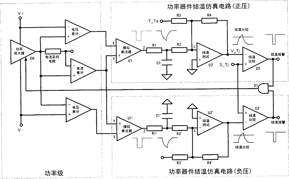
The invention discloses a junction temperature simulation circuit for semiconductor power devices. The junction temperature simulation circuit is characterized in that junction temperature rise of the power devices are dynamically simulated by the junction temperature simulation circuit by the aid of integrating voltages on RC (resistance-capacitance) integrators; an RC time constant of the circuit is equal to thermal response time of thermal models; output of voltages of the circuit and junction temperatures of power devices in the thermal models are in simple linear relations with one another; the circuit has an ambient temperature compensation function; electrics-to-thermal simulation can be completed by the circuit in various working modes such as constant-direct-current working modes, single-pulse working modes, repetitive-pulse working modes and optional-waveform working modes; power level cutting and alarm signals can be provided by the circuit under junction temperature over-limit conditions; normal work of power levels can be automatically recovered by the circuit when the normal junction temperatures are recovered. The junction temperature simulation circuit has the advantages that the thermal models of the power devices are simulated by electric models of the integrators by the aid of a principle that charging formulas of RC integrating circuits in the electrics are approximately identical to temperature rise formulas in the thermal physics, and accordingly real-time junction temperature information of the power devices can be obtained.

Description

technical field [0001] The invention discloses a semiconductor power device junction temperature simulation circuit, its function and performance are suitable for occasions where the semiconductor power device junction temperature needs to be monitored in real time in special test equipment for semiconductor devices, and is also suitable for other occasions where the semiconductor power device junction temperature needs to be monitored in real time liter demand. Background technique [0002] Semiconductor power devices will increase their junction temperature due to their own power consumption during application. When the junction temperature is higher than the specified maximum junction temperature, it may cause damage. Therefore, power amplifiers that use power devices need to give power The device takes heat dissipation measures (such as adding a radiator and ventilation), and on the other hand, it is necessary to limit the user's use conditions for the power amplifier (s...

Claims


Application Information

Patent Timeline
IPC IPC(8): G01K7/00
Inventor 孙铣周鹏王金亮
Owner BEIJING HUAFENG TEST & CONTROL TECH CO LTD
Learn More