Eureka AIR delivers breakthrough ideas for toughest innovation challenges, trusted by R&D personnel around the world.

Production method of grating electrode of solar cell

A solar cell and grid line technology, applied in circuits, photovoltaic power generation, electrical components, etc., can solve the problems of time-consuming and labor-intensive silicon substrates, increase production costs, and difficult to achieve fine film printing, and achieve good quality and production yield. high effect

Active Publication Date: 2015-05-20
福建金石能源有限公司
View PDF6 Cites 5 Cited by
  • Summary
  • Abstract
  • Description
  • Claims
  • Application Information

AI Technical Summary

Problems solved by technology

Printing with silver paste needs to install a template on the silicon substrate of the cell, so the grid electrode prepared by this method often has a negative effect on the printing paste during the printing process due to the latitude and longitude nodes of the template itself. It will lead to non-uniform wire diameter of fine grid lines after printing; and the thickness of the printing template is not easy to control, and it is difficult to achieve fine film printing. These factors will ultimately affect the light conversion rate of solar cells
The defects of the above-mentioned preparation process can be eliminated by pasting dry film on the silicon substrate of the battery and then exposing, developing and electroplating. However, the area of ​​the dry film used in this process is usually larger than the area of ​​the silicon substrate. Since the dry film is opaque, it is difficult to The position of the silicon substrate under the dry film is also difficult to determine
The existing process is to cut off the excess dry film around the silicon substrate and then install a mask on it. This process is time-consuming and laborious and may damage the silicon substrate and increase production costs.

Method used

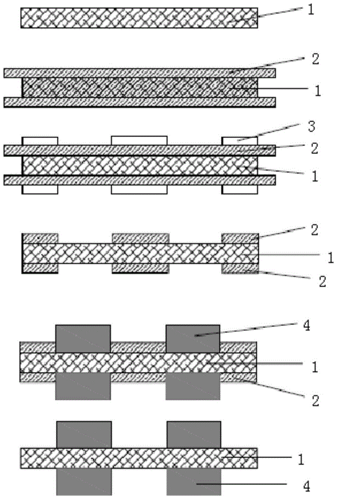
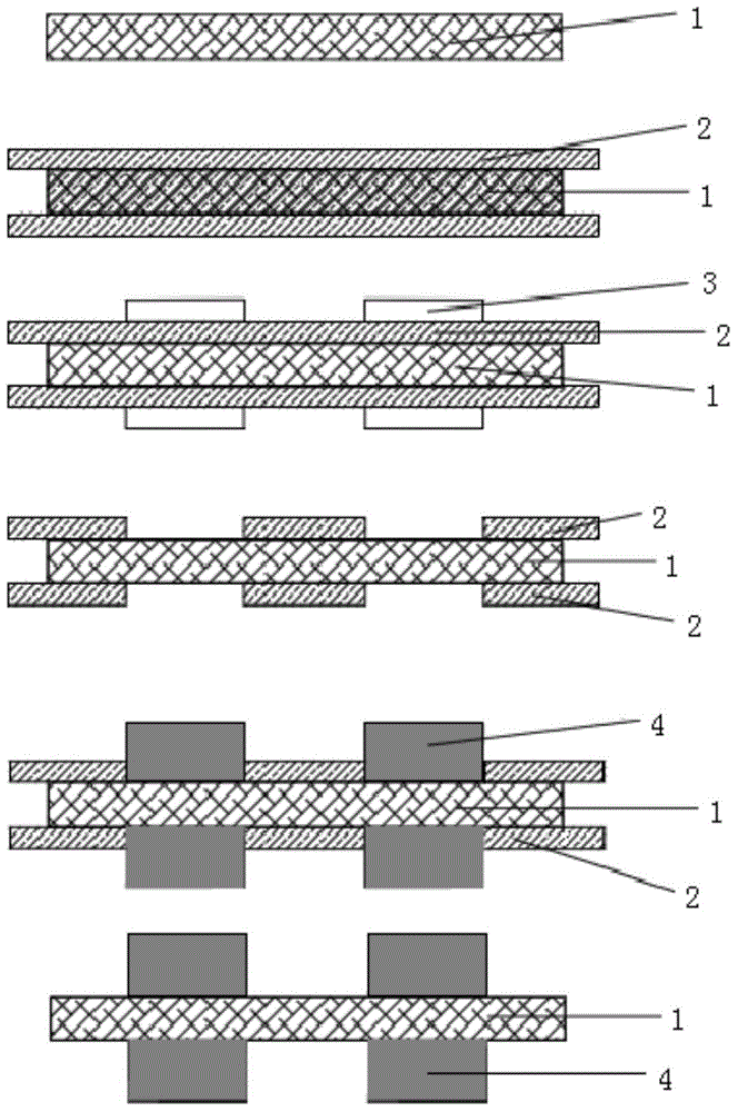
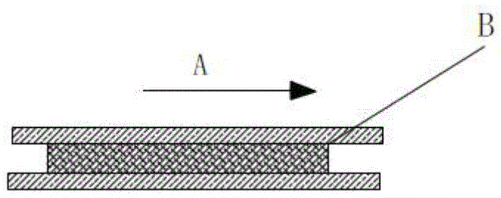

Image

  • Production method of grating electrode of solar cell
  • Production method of grating electrode of solar cell
  • Production method of grating electrode of solar cell

Examples


Embodiment Construction

[0018] In order to make the object, technical solution and advantages of the present invention clearer, the present invention will be further described in detail below in conjunction with the accompanying drawings and embodiments. It should be understood that the specific embodiments described here are only used to explain the present invention, not to limit the present invention.

[0019] refer to Figure 1-2 The method for preparing solar cell grid electrodes of the present invention comprises the following steps: coating a layer of photosensitive dry film 2 on both sides of the silicon substrate 1 of the solar cell, specifically, the thickness of the dry film 2 is 10-100 μm After the film is pasted, the dry film 2 is flattened so that the dry film 2 is closely attached to the silicon substrate 1 . The silicon substrate 1 may be a silicon substrate on which a transparent conductive oxide film and a seed metal film are deposited through PVD.

[0020] A mask plate 3 with req...


PUM


Abstract

The invention discloses a production method of a grating electrode of a solar cell. The production method includes the steps of attaching two dry photosensitive films to two sides of a silicon substrate, respectively; determining a specific position of the silicon substrate between the dry photosensitive films, and mounting a mask, which has a grating grid pattern required, on the dry photosensitive films; according to the determined position of the silicon substrate, fully overlapping the mask and the silicon substrate; exposing the dry photosensitive films on the silicon substrate; transferring the grid pattern of the mask to the surface of one dry photosensitive film; developing the silicon substrate which is exposed, so as to form the grating grid pattern on the surface of the silicon substrate; plating conductive material on the grating grid pattern on the surface of the silicon substrate so as to form the grating electrode. The production method has the advantages that shearing peripheral residual dry films from the silicon substrate of the cell is not required, damage of the silicon substrate is avoided, the method is simple, positioning is accurate and yield is high.

Description

technical field [0001] The invention relates to the field of solar cell preparation, in particular to the preparation of solar cell grid wire electrodes. Background technique [0002] The solar cell includes a supporting solar cell sheet and surface electrodes connected to the cell sheet, and the current generated by the cell sheet is exported through the electrode. In order to reduce the power loss derived from the current and improve the solar energy conversion rate, the electrodes of the solar cells used are mostly grid-line electrodes in a grid pattern. (busbar), the sub grid line and the bus bar line are cross-connected as a whole; the current generated by the battery sheet through the photoelectric effect is collected on the sub grid line, and the sub grid line collects the current on the bus bar line and finally flows out. [0003] In the past, grid line electrodes were made by printing silver paste on the surface of the silicon substrate of the battery, and then sin...

Claims


Application Information

Patent Timeline
IPC IPC(8): H01L31/18H01L31/0224
CPCH01L31/022425H01L31/18H01L31/1876Y02E10/50Y02P70/50
Inventor 林朝晖王树林
Owner 福建金石能源有限公司
Why Eureka
Eureka Blog
Learn More