Polarization Converter Based on Multilayer Frequency Selective Surface

A frequency selective surface and converter technology, applied in the microwave field, can solve the problems of complex structure, high loss and high cost of electrically modulated polarization converters, and achieve the advantages of improving polarization and angular stability, enhancing angular stability and avoiding loss. Effect

Active Publication Date: 2017-10-24
XIDIAN UNIV
View PDF6 Cites 4 Cited by
  • Summary
  • Abstract
  • Description
  • Claims
  • Application Information

AI Technical Summary

Problems solved by technology

[0004] The purpose of the present invention is to address the shortcomings of the above-mentioned prior art, and provide a polarization converter based on a multilayer frequency selective surface, which can solve the problem of complex structure and loss of the electrical control polarization converter while ensuring high performance. and high cost

Method used


Image

  • Polarization Converter Based on Multilayer Frequency Selective Surface
  • Polarization Converter Based on Multilayer Frequency Selective Surface
  • Polarization Converter Based on Multilayer Frequency Selective Surface

Examples


Embodiment 1

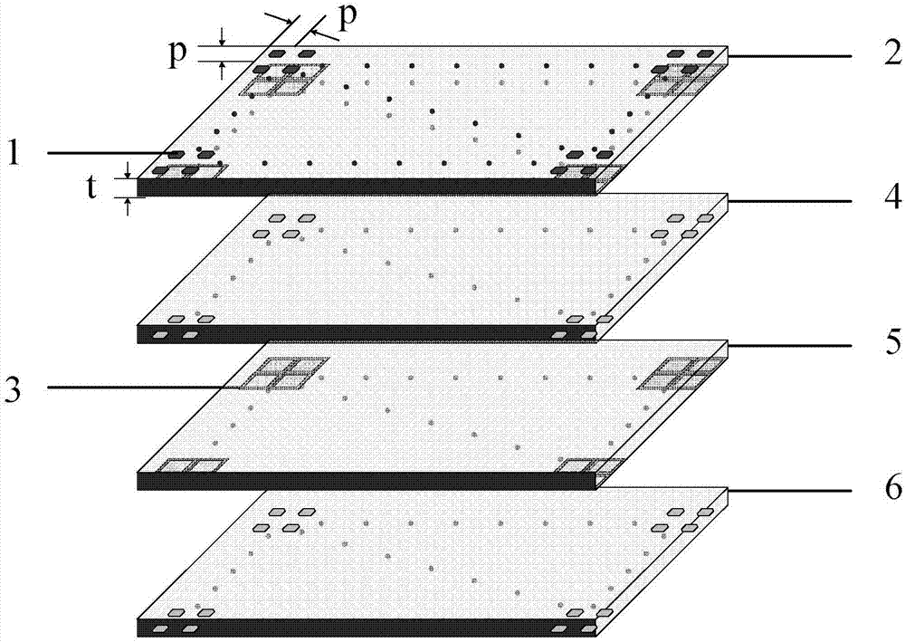
[0024] refer to figure 1 , the first dielectric plate 2, the second dielectric plate 4, the third dielectric plate 5 and the fourth dielectric plate 6 are all made of polytetrafluoroethylene material, and its relative permittivity ε r =2.6±0.05, dielectric loss tanδ=0.015, substrate thickness t=1.5mm; printed on the upper surface of the first dielectric plate 2, the lower surface of the second dielectric plate 4 and the lower surface of the fourth dielectric plate 6 respectively A patch array 1 composed of 8×8 corner-cut square patches 11; the lower surface of the first dielectric plate 2 and the lower surface of the third dielectric plate 5 are printed with 8×8 metal square rings 33 The grid array 3; the first dielectric board 2, the second dielectric board 4, the third dielectric board 5 and the fourth dielectric board 6 are fixed from top to bottom by heat pressing with insulating adhesive material or using media screws, Forming a stacked structure up and down, this multi-...

Embodiment 2

[0028] Embodiment 2 has the same structure as Embodiment 1, only the following parameters are adjusted:

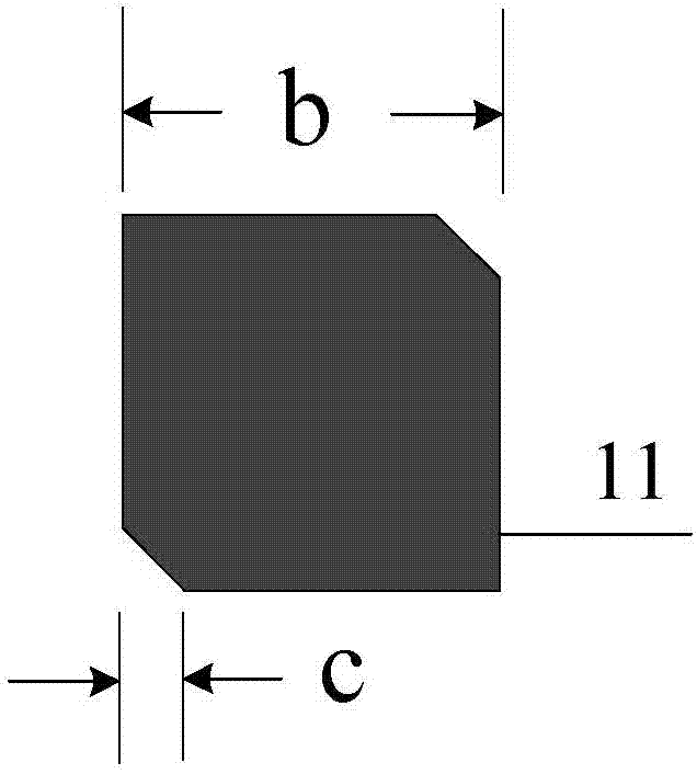
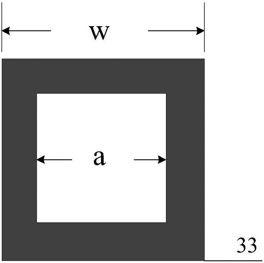
[0029] The four-layer dielectric boards 2, 4, 5 and 6 all adopt Teflon (tm), and its relative permittivity ε r =2.1, dielectric loss tanδ=0.001, substrate thickness t=1mm; number of periodic units M×N=2×2 forming patch array 1 and grid array 3, period p=8mm; square patch 11 side length b =5mm, the side length of the cut corner c=1.5mm; the outer side length w=8mm of the square ring 33, and the inner side length a=6mm.

Embodiment 3

[0031] Embodiment 3 has the same structure as Embodiment 1, only the following parameters are adjusted:

[0032] The four-layer dielectric boards 2, 4, 5 and 6 all adopt Taconic CER-10(tm), and its relative permittivity ε r =10, dielectric loss tanδ=0.035, substrate thickness t=3mm; number of periodic units M×N=128×128 that make up patch array 1 and grid array 3, period p=20mm; square patch 11 side length b =15mm, the side length of the cut corner c=5mm; the outer side length w=20mm of the square ring 33, and the inner side length a=16mm.

[0033] Effect of the present invention is further described below in conjunction with simulation result:

[0034] 1. Simulation content: using Ansys HFSS 13.0, for example Figure 4 The simulation model of the shown embodiment 1 performs full-wave simulation. In the 8.5GHz-11GHz frequency band, a standard gain horn is used as a transmission source, and the emitted linear polarized wave is vertically irradiated on the polarization converte...


PUM


Abstract

The invention provides a polarization converter based on a multi-layer frequency selective surface, which is used to solve the problems of complex structure and high loss of the electrically adjustable polarization converter; on the upper surface of the first dielectric plate (2), the second dielectric The lower surface of the board (4) and the lower surface of the fourth dielectric board (6) are respectively printed with a patch array (1) composed of M×N corner-cutting square patches (11), and the first dielectric board ( 2) The lower surface and the lower surface of the third dielectric board (5) are printed with a grid array (3) consisting of M×N metal square rings (33); the four-layer dielectric board (2, 4, 5, 6) A stacked structure is sequentially formed from top to bottom. In the present invention, the angle between the polarization converter and the polarization direction of the incident ray polarized wave can be adjusted by rotation, so that the incident wave can be converted into left-handed circular polarization, right-handed circular polarization, or linear polarization. Wave characteristics. The invention can be applied to fields such as wireless communication and satellite communication.

Description

technical field [0001] The invention belongs to the field of microwave technology, and relates to a polarization converter, in particular to a high-frequency X-band polarization converter based on a multi-layer frequency selective surface, which can realize the selection and conversion of electromagnetic wave polarization, and is suitable for wireless Communications and satellite communication systems. Background technique [0002] In various antenna systems, it is usually necessary to switch between different polarization states to obtain polarized waves in polarization states such as linear polarization, left-handed circular polarization, or right-handed circular polarization. With the development of wireless communication and satellite communication, the importance of the antenna system to the entire communication equipment is more significant, and antennas with characteristics such as low profile, polarization selection, conversion, high gain and sufficient bandwidth wil...

Claims


Application Information

Patent Timeline
Patent Type & Authority Patents(China)
IPC IPC(8): H01P1/165H01P1/17H01Q15/24
Inventor 李龙巫钊李永久
Owner XIDIAN UNIV
Why Eureka
Try Eureka