
Overheating protection circuit and overheating protection method based on speed command voltage

A speed command, overheat protection technology, applied in electrical components, motor control, electronic commutation motor control and other directions, can solve the problems of complex circuit, burning of motor intelligent power module, good price, etc., to achieve the effect of high controllability

Active Publication Date: 2015-05-20
芜湖卧龙家用电机有限公司
View PDF7 Cites 4 Cited by
  • Summary
  • Abstract
  • Description
  • Claims
  • Application Information

AI Technical Summary

Problems solved by technology

[0005] The above-mentioned patents all use a comparator as a key device to adjust the speed command voltage Vsp, which is expensive, complicated circuit, and impractical; moreover, when the overheating protection starts, the Vsp voltage is directly pulled below 1V to stop the motor. When the overheating protection lowers Vsp forcibly, because the motor stops, the air conditioner cannot receive FG feedback, and will continue to increase the Vsp voltage. When the overheating protection is released, because the air conditioner inputs Vsp to the motor too high, the intelligent power module of the motor will Burned during startup; In addition, the above-mentioned patent places an NTC-type temperature sensor on the surface of the smart power chip, which is difficult to operate in practical applications, and the measured data is not very accurate

Method used


Image

  • Overheating protection circuit and overheating protection method based on speed command voltage
  • Overheating protection circuit and overheating protection method based on speed command voltage
  • Overheating protection circuit and overheating protection method based on speed command voltage

Examples


Embodiment Construction

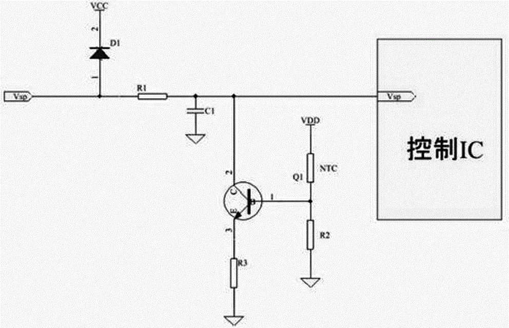
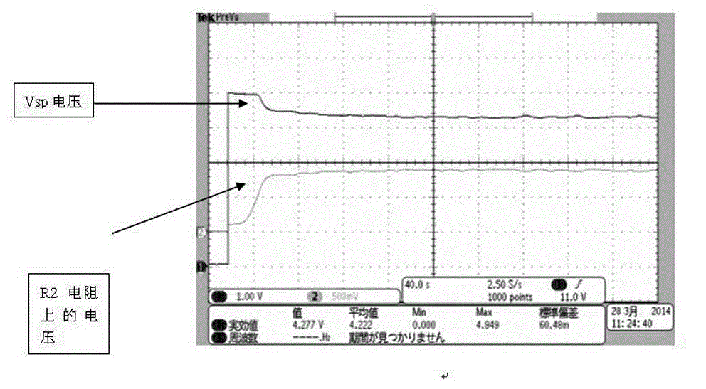
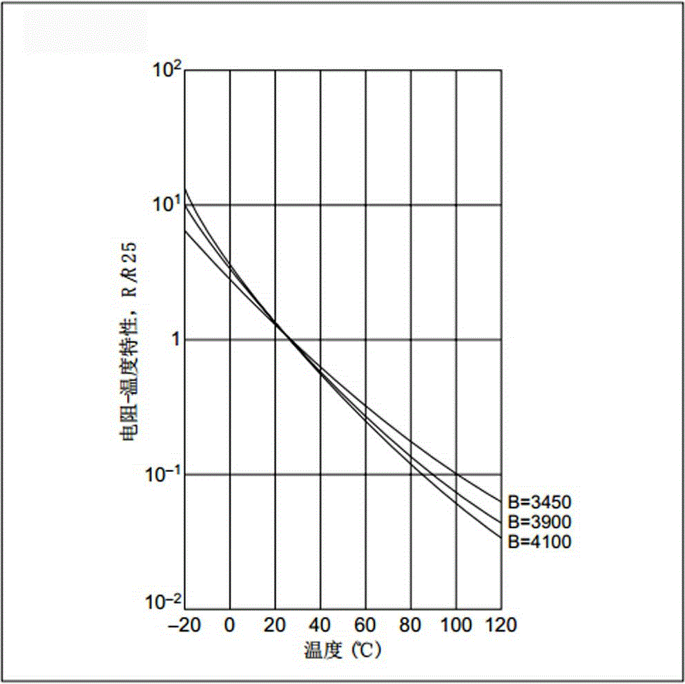
[0023] Please refer to Figure 1 to Figure 3 , the general voltage range of the speed command voltage Vsp is between 2.1V and 5.4. When the speed command voltage Vsp rises, the effective value of the motor terminal voltage increases, and the output power increases; when the speed command voltage Vsp decreases, the effective value of the motor terminal voltage decreases, the output power decreases. Adjusting the speed command voltage Vsp is the most effective way to control the conversion of the motor output power.

[0024] After the speed command voltage Vsp enters the motor, it first passes through a clamping diode D1 to filter out the large voltage surge to ensure that the speed command voltage Vsp is less than VCC+0.7V, and then the speed command voltage Vsp passes through a low-pass RC filter circuit to filter out High frequency small signal interference. 1.2KΩ and 0.02uF are recommended for this RC parameter. If the time constant is selected too large, there will be re...


PUM

PropertyMeasurementUnit
Filter capacitoraaaaaaaaaa
Thermistoraaaaaaaaaa

Abstract

The invention discloses an overheating protection circuit based on speed command voltage. The circuit is positioned between peripheral speed command voltage Vsp and chip speed signal input voltage Vsp; the circuit comprises a current clamping diode D1, an RC filter circuit, an NPN triode Q1, a buffer resistor R3, a thermistor NTC and a divider resistor R2, wherein the RC filter circuit comprises a filter resistor R1 and a filter capacitor C1; a main circuit forms between the peripheral speed command voltage Vsp and the chip speed signal input voltage Vsp; one end of the current clamping diode D1 is connected to the main circuit, and the other end of the current clamping diode D1 is communicated with a power supply Vcc; the filter resistor R1 is connected to the main circuit in series, one end of the filter capacitor C1 is connected to the main circuit, and the other end of the filter capacitor C1 is grounded; the C electrode of the NPN triode Q1 is connected to the main circuit, the E electrode of the NPN triode Q1 is connected to the buffer resistor R3, and the B electrode of the NPN triode Q1 is respectively connected to the thermistor NTC and the divider resistor R2; the thermistor NTC is simultaneously connected with VDD, and the voltage divider resistor R2 is simultaneously grounded. The overheating protection circuit has the advantages of high controllability, stability and reliability, and an integrated power chip is protected from being damaged by thermal shock.

Description

technical field [0001] The invention relates to an overheat protection circuit and an overheat protection method of a brushless DC motor for an air conditioner. Background technique [0002] At present, there are two types of overheating protection schemes for brushless DC motors used in air conditioners. A protection method by applying overheat protection to the reset circuit. Generally, a voltage hysteresis is set in the reset circuit to prevent malfunction. Because the internal temperature of the motor cannot change suddenly, this voltage hysteresis causes the motor to appear fast and slow in speed under certain conditions, and even stop and turn sometimes. Another way is to apply overheating protection to the current limiting protection circuit. This method uses a PTC thermistor, and due to the temperature resistance characteristics of the element, the action range of the overheating protection is relatively large. And this method will limit the current capability o...

Claims


Application Information

Patent Timeline
IPC IPC(8): H02P29/00H02P6/00
Inventor 胡锋前谷达男余健王兴龙陈国红胡凌剑王辉
Owner 芜湖卧龙家用电机有限公司
Learn More