
A LED drive circuit that regulates the current in a full range and corrects the dimming curve

A dimming curve and current regulating technology, applied in the direction of lamp circuit layout, electric light source, light source, etc., can solve the problems of small dimming range, complex circuit, poor brightness consistency, etc., and achieve good electromagnetic compatibility, simple circuit structure, The effect of wide dimming range

Active Publication Date: 2018-05-22
SHANGHAI AVIATION ELECTRIC
View PDF4 Cites 0 Cited by
  • Summary
  • Abstract
  • Description
  • Claims
  • Application Information

AI Technical Summary

Problems solved by technology

Voltage dimming is to adjust the brightness by changing the voltage at both ends of the LED, but the dimming range is small, and the brightness consistency is poor when dimming multiple lamps; because the current rises after the LED heats up, the reliability of the LED is affected, and it is only suitable for small power and heat generation. small lamps
PWM dimming adjusts the brightness by controlling the on-off ratio of the LED under constant current, which has high efficiency and high dimming accuracy, but only the single-chip microcomputer and software can achieve stable 1% to 100% wide-range brightness adjustment and uniform dimming The human-machine effect, the circuit is relatively complex, and the volume is large. It is generally used for large-scale lamps. The PWM dimming frequency is between 200 and 20kHz. The electromagnetic interference generated by the low-frequency band cannot meet the electromagnetic compatibility requirements of all military platform aircraft.

Method used


Image

  • A LED drive circuit that regulates the current in a full range and corrects the dimming curve
  • A LED drive circuit that regulates the current in a full range and corrects the dimming curve
  • A LED drive circuit that regulates the current in a full range and corrects the dimming curve

Examples


Embodiment Construction

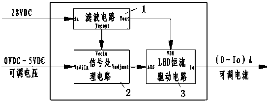
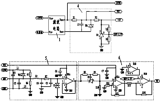
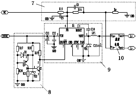
[0011] The circuit of the present invention includes a first filter circuit 1, a signal processing circuit 2 and a LED constant current drive circuit 3, the input end of the signal processing circuit is connected to the adjustable voltage input end, the output end of the signal processing circuit is connected to the LED constant current The input end of the drive circuit is connected, the output end of the LED constant current drive circuit is connected to the adjustable current output end, and the first filter circuit 1 performs filter processing on the on-board DC power supply 28VDC to provide the signal processing circuit and the LED constant current drive circuit. Operating Voltage. Its working principle block diagram is as follows figure 1 shown.

[0012] 28VDC on-board DC power supply through figure 1 The processing shown in the first filter circuit 1 enters the signal processing circuit and the LED constant current drive circuit. The signal is processed by the voltag...


PUM


Abstract

The present invention relates to an LED drive circuit for adjusting current in a full range and correcting dimming curve, including a filter circuit 1, a signal processing circuit, and an LED constant current drive circuit, characterized in that the signal processing circuit includes a voltage reference circuit, a filter circuit 2 and The dimming curve correction circuit; the LED constant current drive circuit includes a delay start circuit, a DC / DC conversion circuit, a feedback circuit and a filter circuit 3 . The advantages of the present invention are: full hardware analog circuit, simple circuit structure, adjustable output current, achievable dimming range of 1% to 100%, conforming to visual man-machine effect, good electromagnetic compatibility, and resistant to various environments and climates Etc. It can be popularized and applied in lighting fields of various fields and industries.

Description

technical field [0001] The patent of the present invention relates to an LED constant current drive circuit, especially an LED drive circuit that regulates the current in a full range and corrects the dimming curve. Background technique [0002] At present, LED lamps with dimming function are widely used in various types of aircraft. There are two commonly used LED dimming driving methods: voltage dimming and PWM dimming. Voltage dimming is to adjust the brightness by changing the voltage at both ends of the LED, but the dimming range is small, and the brightness consistency is poor when dimming multiple lamps; because the current rises after the LED heats up, the reliability of the LED is affected, and it is only suitable for small power and heat generation. Small light fixtures. PWM dimming adjusts the brightness by controlling the on-off ratio of the LED under constant current, which has high efficiency and high dimming accuracy, but only the single-chip microcomputer a...

Claims


Application Information

Patent Timeline
Patent Type & Authority Patents(China)
IPC IPC(8): H05B37/02
Inventor 张梦芬周海英刘晓东
Owner SHANGHAI AVIATION ELECTRIC
Learn More