fishing reel

A reel and fishing line technology, applied in fishing reels, fishing, applications, etc., can solve the problems of fishing line sinking effect, sensitivity and operability influence, coating peeling, uneven release force, etc. Achieving the effects of miniaturization and simplification, prevention of reduction in release performance, and improved operability

Active Publication Date: 2017-08-08
DAIWA SEIKO CORPORATION
View PDF2 Cites 1 Cited by
  • Summary
  • Abstract
  • Description
  • Claims
  • Application Information

AI Technical Summary

Problems solved by technology

Therefore, the fishing line may be damaged
Moreover, when the fishing line is a PE line, the coating may also peel off
In addition, since the level winding device is also loaded by the fishing line guide, it may also become a cause of failure.
[0008] Also, depending on the position of the fishing line guide in the left and right directions, there may be unevenness in the discharge force, which may also affect the sinking effect, sensitivity, and operability of the fishing line. There is a need to improve these

Method used


Image

  • fishing reel
  • fishing reel
  • fishing reel

Examples


no. 1 Embodiment approach

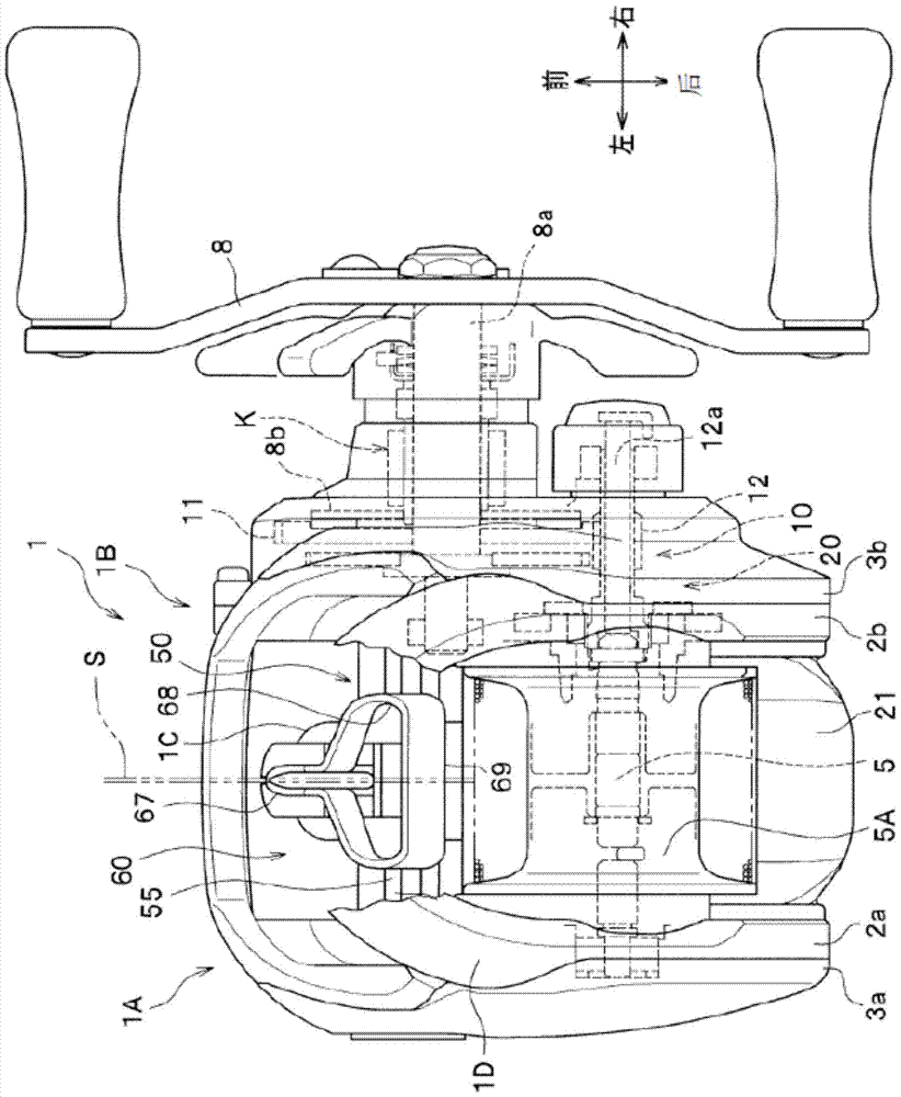
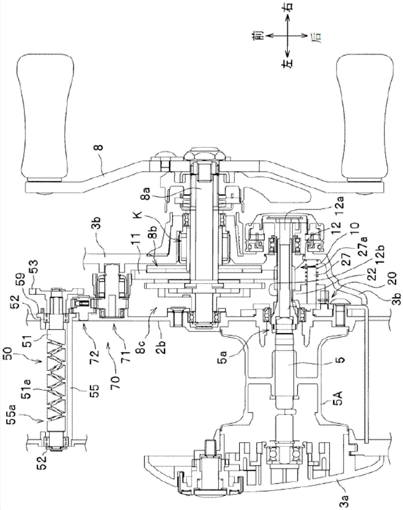
[0053] like figure 1 As shown, the fishing reel according to this embodiment has a reel body 1 including left and right side plates 1A, 1B. The left and right side plates 1A, 1B are configured to cover the left and right frames 2a, 2b with the left and right cover plates 3a, 3b. The reel body 1 is integrally formed with a reel leg 1C, which is located between the left and right side plates 1A, 1B and attached to a fishing rod not shown. In addition, a spool shaft 5 is rotatably supported via bearings between the left and right frames 2a, 2b, and a spool 5A around which a fishing line S is wound is integrally fixed to the spool shaft 5. Furthermore, between the left and right side plates 1A, 1B, a thumb rest (Thumb Rest) 1D on which fingers can be placed is provided on the upper side with respect to the roll 5A.

[0054] In this embodiment, the handle 8 for rotating the drive drum 5A is provided on the right side plate 1B side. A space is formed between the right frame 2b an...

no. 2 Embodiment approach

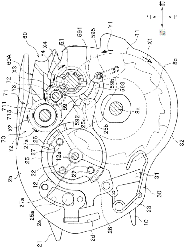
[0119] Figure 13 to Figure 16 A fishing reel according to the second embodiment is shown. This embodiment differs from the above-mentioned first embodiment in that the one-way gear 71A of the switching mechanism 70 is directly attached to the pinion 12 . That is, in this embodiment, if Figure 13 As shown, the one-way gear 71A is rotated by the rotation of the pinion gear 12 , and the rotational force of the one-way gear 71A is transmitted to the rotating plate 59 via the friction gear 72 . Furthermore, the friction gear 72 has only a larger diameter than that of the first embodiment, and its structure and function are the same. In addition, the rotating plate 59 and its peripheral structure are also the same as those of the first embodiment.

[0120] like Figure 14 As shown, the one-way gear 71A includes: a one-way clutch 712A; and an output gear 711 provided via the one-way clutch 712A. The one-way gear 71A is constituted as follows, when the pinion gear 12 rotates in...

no. 3 Embodiment approach

[0140] Figure 17 , Figure 18 A fishing reel according to a third embodiment is shown. This embodiment differs from the above-mentioned first and second embodiments in that the switching mechanism 70 is provided on the cord reel body 1 provided with a known lever force release mechanism 80 . like Figure 17 As shown, the spool shaft 5 is supported on the left cover 3a in a rotationally fixed manner by the pin 5c, and the spool 5A is rotatably supported on the spool shaft 5 . like Figure 17 As shown, the rod force release mechanism 80 is arranged on the right side of the spool shaft 5 (support shaft) at the side of the right frame 2b. The force release of the rod force release mechanism 80 can be adjusted by rotating the rod 81 in the front and rear direction. The lever force release mechanism 80 is constituted as follows, by adjusting the pressing force of the force release piece on the side of the retraction drive portion of the brake portion with the rod 81 through a ...


PUM


Abstract

The present invention provides a fishing line reel, which can reduce the load acting on the level winding device, improve the sinking effect and sensitivity of the fishing line, and can improve the operability of fishing. More specifically, it has: a uniform winding device, which reciprocates the fishing line guide body left and right in order to guide the fishing line to the reel; part and a wide opening, and when the fishing line is wound up in the spool, the fishing line is guided on the narrow guide part, and when the fishing line is released from the spool, the fishing line is positioned on the It is guided by a wide opening and equipped with a switching mechanism for switching the posture of the fishing line guide. In the state where the fishing line is wound up in the spool, when the fishing line is drawn out against the force release of the force release device, the The posture of the fishing line guide is switched by the switching mechanism so that the guiding position of the fishing line is changed from the narrow guide portion to the wide opening.

Description

technical field [0001] The present invention relates to a fishing reel provided with a fishing line guide between side plates in front of a spool. Background technique [0002] Conventionally, in order to evenly wind a fishing line around a spool rotatably supported between left and right side plates, a level winding device has been disposed on a double bearing type fishing reel. This level winding device includes a fishing line guide that reciprocates left and right in front of the spool in conjunction with the retracting operation of a handle that is rotatably disposed on one side plate side. By passing the fishing line through the fishing line guide, Thereby, the fishing line can be wound parallel to the spool. [0003] However, the above-mentioned fishing line guide has the following problems. For example, when casting the hook assembly, the fishing line contacts to generate resistance, which reduces the throwing distance of the hook assembly. In order to solve such a ...

Claims


Application Information

Patent Timeline
Patent Type & Authority Patents(China)
IPC IPC(8): A01K89/01
CPCA01K89/01A01K89/0108A01K89/0117A01K89/0187A01K89/01912A01K89/01918
Inventor 梅沢雄一东本隆
Owner DAIWA SEIKO CORPORATION
Why Eureka
Try Eureka