Aircraft

A technology for aircraft and thrusters, applied in the field of aircraft, can solve problems such as inability to provide structural efficiency

Active Publication Date: 2015-06-03
ROLLS ROYCE PLC
View PDF3 Cites 16 Cited by
  • Summary
  • Abstract
  • Description
  • Claims
  • Application Information

AI Technical Summary

Problems solved by technology

However, these concepts offer only relatively limited fuel efficiency benefits and do not provide significant or any structural efficiency improvements over conventional designs

Method used


Image

  • Aircraft
  • Aircraft
  • Aircraft

Examples


Embodiment Construction

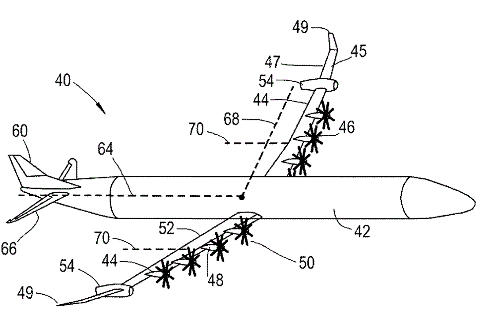
[0031] refer to figure 2 A first aircraft 40 is shown. The aircraft includes a fuselage 42 ; a pair of wings 44 extending generally perpendicular to and extending from the fuselage 42 ; and an empennage located aft of the fuselage 42 . The tailplane comprises vertical and horizontal tailplanes 60 , 66 .

[0032] Wingspan is defined by the distance between wingtips 49 . Each airfoil 44 includes a leading edge 45 and a trailing edge 47 which together define a chord extending therebetween. The ratio of the wingspan to the chord length defines the aspect ratio. as from figure 2 As can be seen, the chord length varies along the span, from a relatively large chord length at the root adjacent to the fuselage 42 to a relatively small length at the wing tip 49 . With the chord varying along the span like this, the aspect ratio AR can be defined as the square of the span b divided by the area S of the wing plane:

[0033]

[0034] Although higher aspect ratios such as up to 3...


PUM


Abstract

An aircraft (40). The aircraft (40) comprises a propulsion system comprising a pair of internal combustion engines (10) each driving an electrical power generator (56), each electrical power generator (56) being electrically coupled to a plurality of electrically driven propulsors (46). The propulsors (46) are located forward of a leading edge (45) of the wings (44) such that an airstream generated by the propulsors flows over the wings (44) in use. Each internal combustion engine (10) and electrical generator (56) is mounted on a respective wing (44) outboard of a centre of thrust (70) of the propulsors (46) on that wing (44).

Description

technical field [0001] The invention relates to an aircraft. In particular, the invention relates to an aircraft with distributed propulsion. Background technique [0002] A conventional aircraft includes a tubular fuselage with wings extending therefrom to provide lift. Engines in the form of, for example, turbofans and turboprops are mounted on aircraft to provide forward thrust. The traditional location for mounting an aircraft engine is on the wing. figure 1 An existing aircraft 1 is shown in , wherein the aircraft 1 includes a fuselage 2 and wings 3 . The aircraft 1 is powered by turboprop engines 4 mounted such that propellers 5 are located in front of the wings 2 and on either side of the fuselage 2 . [0003] There is a continuing need for more efficient aircraft designs in terms of: structural efficiency (i.e., minimizing the overall weight of the aircraft structure), aerodynamic efficiency (i.e., minimizing aerodynamic drag generated during flight), and fuel ef...

Claims


Application Information

Patent Timeline
Patent Type & Authority Applications(China)
IPC IPC(8): B64D27/02B64D29/02
CPCB64D27/12B64D27/24Y02T50/60Y02T50/40B64C3/00B64C3/28B64C9/18B64C11/00B64C23/005B64D27/10
Inventor M. 默克森
Owner ROLLS ROYCE PLC
Why Eureka
Try Eureka