Carbon disulfide reacting furnace

A carbon disulfide and reaction furnace technology, applied in the field of carbon disulfide production, can solve the problems of limited production efficiency, small reaction chamber, high energy consumption, etc., and achieve the effects of improving production efficiency, increasing production capacity, and increasing capacity

Active Publication Date: 2015-06-03
濮阳天泓实业有限公司
View PDF9 Cites 20 Cited by
  • Summary
  • Abstract
  • Description
  • Claims
  • Application Information

AI Technical Summary

Problems solved by technology

[0005] Due to structural reasons, especially due to heat source conduction, the reaction chambers of the above-mentioned reactors are relatively small, thus limiting the production capacity of a single device, especially the production efficiency is greatly limited. Therefore, in order to ensure the output, the main It is to expand the production capacity by increasing the number of reactor sets, which limits the production capacity and keeps the energy consumption high

Method used


Image

  • Carbon disulfide reacting furnace
  • Carbon disulfide reacting furnace
  • Carbon disulfide reacting furnace

Examples


Embodiment 1

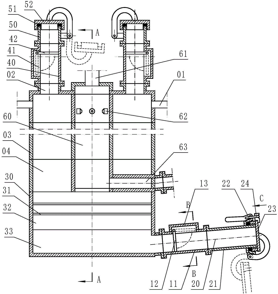
[0029] Example 1: Reference Figure 1 ~ Figure 4 , Is a schematic diagram of the structure of embodiment 1 of the present invention, including a furnace body 03, a reaction chamber 04, a furnace bottom 30, a discharge port 01 and a slag discharge port 20. The furnace body 03 is circular and is composed of a plurality of nodal members combined into a cylinder The furnace body 03 and the furnace bottom 30 are combined to form the reaction chamber 04. The central part of the reaction chamber 04 is provided with a vertical central heating chamber 60. The central heating chamber 60 includes an air inlet 61 and a smoke outlet 63. In this embodiment, the air inlet 61 is provided in the upper part of the reaction chamber 04, the smoke outlet 63 is provided in the lower part of the reaction chamber 04, and a heater 62 is provided in the central heating chamber 60. The heater 62 in this embodiment is a gas heater .

[0030] Four feeding ports 02 are provided on the upper part of the react...

Embodiment 2

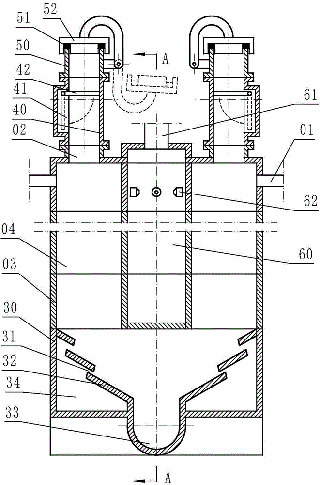
[0038] Example 2: Reference Figure 5 , Is a schematic diagram of the structure of Embodiment 2 of the present invention. Compared with Embodiment 1, the difference of this embodiment is that: the slag tank 33 and the slag tap 20 are both inclined upward and the bottom is in a straight line. The partition 32 between the 33 and the sulfur gasification chamber 34 is made of strip-shaped plates stacked up and down to form a louver shape, and there are vertical connecting reinforcing ribs in the middle.

Embodiment 3

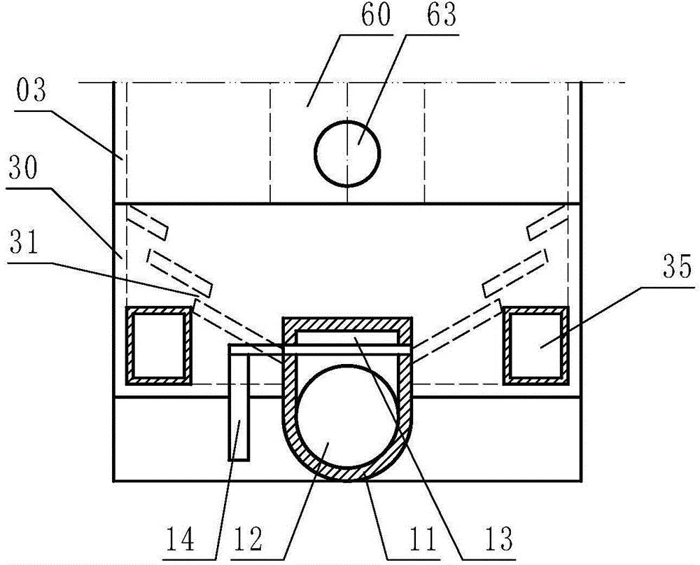
[0039] Example 3: Reference Image 6 , Figure 7 , Is a schematic structural diagram of Embodiment 3 of the present invention. Compared with Embodiment 1 or 2, the difference of this embodiment is that the pores 31 of the partition plate 32 between the slag tank 33 and the sulfur gasification chamber 34 are circular Hole, the hole in the partition 32 from the sulfur gasification chamber 34 to the slag tank 33 is inclined from top to bottom, and the upper edge of the slag tank 33 side of the air hole 31 can completely cover the sulfur gasification chamber 34 The bottom edge of one side.


PUM


Abstract

The invention discloses a carbon disulfide reacting furnace. The carbon disulfide reacting furnace comprises a furnace body (03), a reaction chamber (04), a furnace bottom (30), a discharge port (01) and a slag notch (20), wherein a vertical central heating chamber (60) is arranged on the central part of the reaction chamber (04), the central heating chamber (60) comprises an air inlet (61) and a smoke outlet (63); a heater (62) is arranged inside the central heating chamber (60); and at least two feeding ports (02) are arranged on the upper part of the reaction chamber (04) and are circled on the surrounding of the central heating chamber (60). Compared with the prior art, the volume of the reaction chamber can be greatly increased, so that the production capacity of a single device can be greatly increased, the production efficiency is improved and the energy consumption is greatly reduced.

Description

technical field [0001] The invention belongs to the technical field of carbon disulfide production, in particular to a production equipment of carbon disulfide, especially a carbon disulfide reaction furnace. Background technique [0002] At present, there are two main types of reaction furnaces for producing carbon disulfide, namely internal heat type and reaction retort type. [0003] The internal heating type mainly uses electric heating, which consumes a lot of power. Reactor as disclosed in CN203998966U, CN203582503U. [0004] The reaction retort formula is then provided with the reaction inner chamber in the heating chamber built by refractory materials, such as the disclosed reaction furnace of CN1071893A, CN2107458U, CN1453210A. [0005] Due to structural reasons, especially due to heat source conduction, the reaction chambers of the above-mentioned reactors are relatively small, thus limiting the production capacity of a single device, especially the production ef...

Claims


Application Information

Patent Timeline
Patent Type & Authority Applications(China)
IPC IPC(8): C01B31/26
Inventor 张贯彪梅淑华梅骢
Owner 濮阳天泓实业有限公司
Why Eureka
Try Eureka