High-speed fuel oil atomizing spray nozzle for thermally spraying fuel gas

A fuel atomization and thermal spraying technology, applied in coating, spraying device, melting spraying and other directions, can solve the problems of unsuitable high-speed flame spraying, complicated nozzle structure and high control requirements, and improve ignition reliability and combustion stability high stability, compact structure, and the effect of improving uniformity

Active Publication Date: 2015-06-03
ACADEMY OF ARMORED FORCES ENG PLA +1
View PDF7 Cites 3 Cited by
  • Summary
  • Abstract
  • Description
  • Claims
  • Application Information

AI Technical Summary

Problems solved by technology

The external mixing nozzle mainly relies on the high-speed flowing gas and liquid flow to atomize under the impact of the nozzle outside. Usually, the nozzle of this structure also uses the mechanical structure to rotate the air flow and liquid flow to produce the centrifugal effect. Therefore, the nozzle The structure is complex and the size is large, so it is not suitable for high-velocity flame spraying
The internal mixing nozzle mainly relies on the high-speed kinetic

Method used


Image

  • High-speed fuel oil atomizing spray nozzle for thermally spraying fuel gas
  • High-speed fuel oil atomizing spray nozzle for thermally spraying fuel gas
  • High-speed fuel oil atomizing spray nozzle for thermally spraying fuel gas

Examples


Embodiment 1

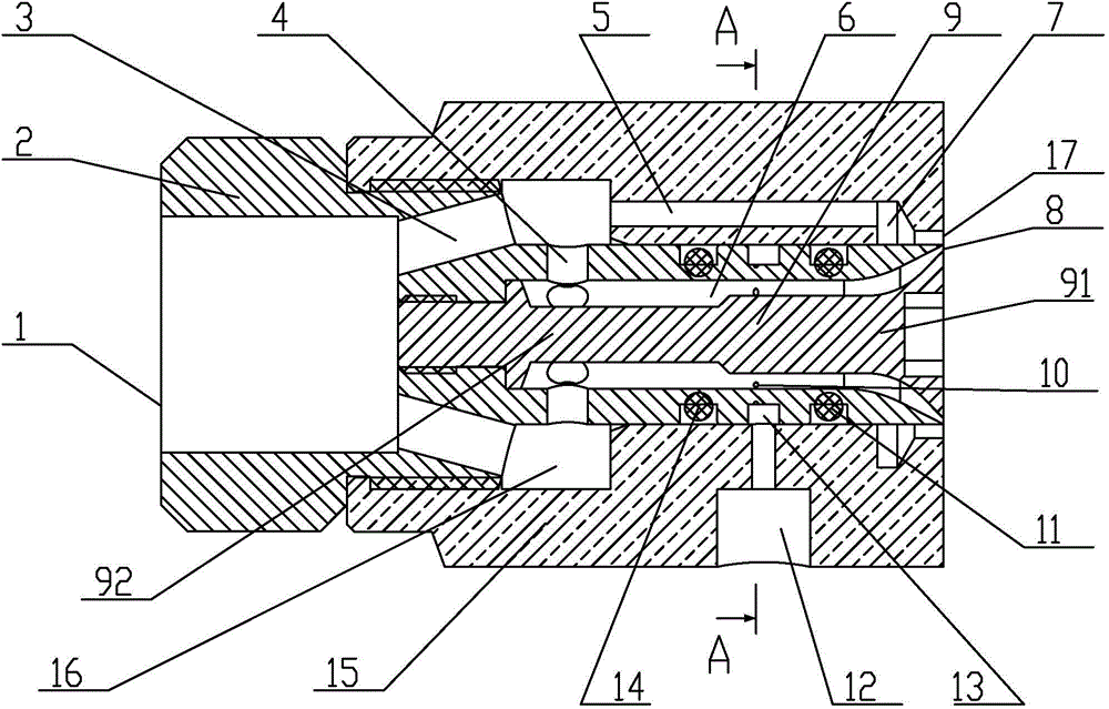
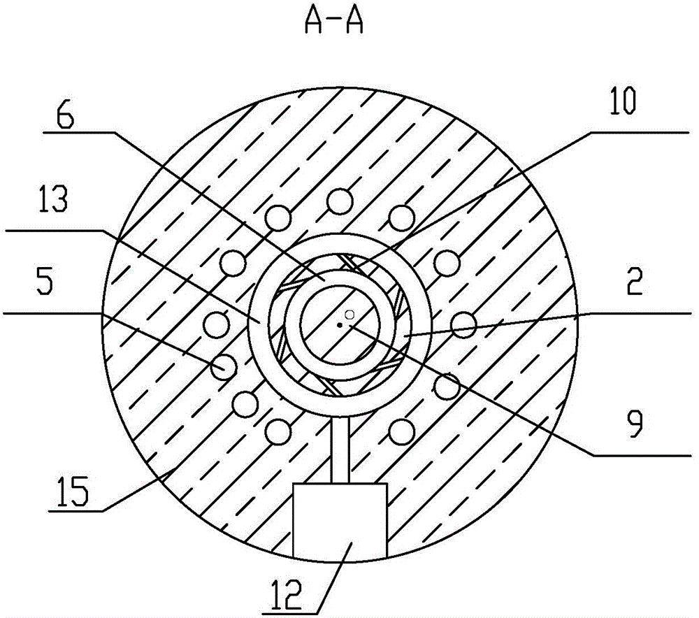
[0023] Such as figure 1 and figure 2 As shown, the nozzle embodiment 1 of the present invention includes a main cavity 2, the outer wall of the main cavity 2 is equipped with a sub-cavity 15, the inlet end of the main cavity 2 is provided with a gas inlet 1 and the outlet end is provided with an inner wall connected to the outside. cavity, the center of the inner cavity is equipped with a cone-like body 9, the cone head 91 of the cone-like body 9 is placed in the opening formed by the inner cavity on the outlet end of the main cavity body 2 and the cone tail 92 is located inside the main cavity body 2, the cone-like body Between the outer wall of 9 and the inner wall of the inner cavity, an annular main chamber 6 that gradually expands to the periphery in a trumpet shape from the inside to the outside is formed, and an annular main spout 8 is formed between the opening at the outlet end of the main cavity 2 and the opening. In order to realize the oblique injection of the mi...

Embodiment 2

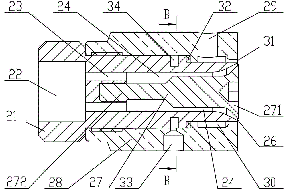
[0027] Such as image 3 and Figure 4 As shown, the nozzle embodiment 2 of the present invention includes a main cavity 21, the outer wall of the main cavity 21 is equipped with a sub-cavity 28, the inlet end of the main cavity 21 is provided with a gas inlet 22 and the outlet end is provided with an inner wall that communicates with the outside. cavity, the center of the inner cavity is equipped with a cone-like body 27, the cone head 271 of the cone-like body 27 is placed at the opening formed by the inner cavity on the outlet end of the main cavity body 21 and the cone tail 272 is located inside the main cavity body 21, the cone-like body Between the outer wall of 27 and the inner wall of the inner cavity, a ring-shaped main chamber 24 gradually expanding from the inside to the outside in a trumpet shape to the periphery is formed, and an annular main spout 26 is formed between the opening of the outlet end of the main cavity 21 and the opening. In order to realize the obl...


PUM


Abstract

The invention discloses a high-speed fuel oil atomizing spray nozzle for a thermally spraying fuel gas. The high-speed fuel oil atomizing spray nozzle comprises a primary cavity, wherein a secondary cavity is assembled on the outer wall of the primary cavity; a gas inlet is formed in the inlet end of the primary cavity, an inner cavity is formed in the outlet end of the primary cavity, a similar cone is mounted in the inner cavity, a ring-shaped primary chamber which is gradually expanded towards the peripheral side in the shape of horn from the inside to the outside is formed between the outer wall of the similar cone and the inner wall of the inner cavity, a ring-shaped primary spray nozzle is formed in an opening in the outlet end of the primary cavity, a gas inlet is communicated with the end part, which is arranged on the inner part of the primary cavity, of the primary cavity through a gas conveying channel, an oil injection hole is formed in the secondary cavity, the oil injection hole is communicated with the middle part of the primary chamber through an oil conveying channel, a ring-shaped secondary chamber for conveying secondary gas flow is formed in the secondary cavity, the secondary chamber is communicated with the outer part through a ring-shaped secondary spray nozzle, the secondary spray nozzle is positioned at the peripheral side of the primary spray nozzle, so that secondary gas flow sprayed out by the secondary spray nozzle and mixed gas flow sprayed out by the primary spray nozzle are crossed at a set included angle and collide. The high-speed fuel oil atomizing spray nozzle is used for atomizing the fuel oil through gas power, so that the gas and the fuel oil are uniformly mixed and atomized, and stably combusted.

Description

technical field [0001] The invention relates to a fuel atomizing nozzle for high-speed gas thermal spraying, which belongs to the technical field of fuel atomizing combustion. Background technique [0002] The thermal spray technology based on the combustion of liquid fuel to generate high-velocity gas can be used for the preparation of metal or non-metallic coatings. This technology usually includes two types: oxygen-assisted combustion high-velocity flame spraying and air-assisted combustion high-velocity flame spraying. The common feature is that liquid fuels such as kerosene Atomization occurs, and at the same time it is mixed with oxygen or air to generate a combustible mixture, which is ignited and burned under the action of an external heat source to generate high-temperature and high-speed gas, which heats and accelerates the deposition of the material to be sprayed to form a coating. [0003] Oxygen-assisted combustion kerosene high-velocity flame spraying technolog...

Claims


Application Information

Patent Timeline
IPC IPC(8): C23C4/12B05B17/04C23C4/129
Inventor 陈永雄梁秀兵徐滨士胡尧强张志彬
Owner ACADEMY OF ARMORED FORCES ENG PLA
Why Eureka
Try Eureka