Flashing liquid-separation integration device

An integrated device and liquid separation technology, which is applied in gas/liquid distribution and storage, pipeline systems, mechanical equipment, etc., can solve problems such as high operating cost, fast liquid discharge speed, and increased liquid volume in liquid separation tanks, so as to improve reliability Sex and stability, shorten the construction period, and reduce the effect of land occupation

Active Publication Date: 2015-06-03
XIAN CHANGQING TECH ENG
View PDF6 Cites 3 Cited by
  • Summary
  • Abstract
  • Description
  • Claims
  • Application Information

AI Technical Summary

Problems solved by technology

[0004] In the actual production and operation process, due to the large amount of upstream liquid and its fluctuations, the liquid separation tank discharge process has a small diameter and the operating pressure is normal pressure, the above liquid separation tank system has the following problems during production and operation: One is that the liquid separation tank is an atmospheric pressure tank, which relies on gravity to flow in, and the drainage speed of the trap is slow. , Insufficient liquid storage capacity, causing the liquid volume of the liquid separation tank to exceed the set value
The second is that when the drain of the trap is not timely or blocked, it needs to be drained manually, so the station needs to be on duty all day long, and the operating cost is high; third, when the gas field is in normal production, the liquid volume is small, so the drain valve, manual ball valve If the caliber of the trap is small, when the venting operation is performed in the station or the amount of liquid coming from the upstream is large, the drainage capacity of the drain valve is insufficient, and the liquid volume in the liquid separation tank increases in a short time, which affects the effect of flash liquid separation, and also causes the raw material gas to transfer oil and water Bring out the torches, forming a "fire rain"
Fourth, when other process equipment such as the separator in the station is draining liquid, and at the same time, the pipeline is vented, the two working conditions are likely to affect each other, and "fire rain" is likely to occur

Method used


Image

  • Flashing liquid-separation integration device

Examples


Embodiment 1

[0025] In order to overcome the existing problems of slow liquid discharge, easy blockage, insufficient liquid storage capacity, and high labor cost, the present invention provides a flash liquid separation integrated device, which has a combined device for flash evaporation, venting liquid separation, and reduces investment. Reduce land occupation and shorten the construction period, and realize automatic liquid drainage under normal operating conditions of the gas gathering station, and emergency liquid drainage capabilities under slug flow conditions, so as to improve the reliability and stability of station operation.

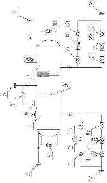
[0026] Such as figure 1 As shown, a flash liquid separation integrated device includes a tank body 25, and the tank body 25 is divided into a flash chamber 1 and a liquid separation chamber 2 through a blockage 9 along the vertical direction;

[0027] One end inlet of the flash chamber 1 communicates with the first liquid inlet 3 through a pipeline, the upp...

Embodiment 2

[0039] On the basis of Embodiment 1, a first electric ball valve 12 connected in parallel with the fourth electric ball valve 15 is also provided between the lower outlet of the flash chamber 1 and the first liquid discharge port 17, and the first electric ball valve 12 is electrically connected to the first liquid level gauge 8, and a first manual ball valve 11 and a second manual ball valve 13 are respectively arranged on the pipelines at both ends of the first electric ball valve 12.

[0040]When the amount of liquid coming from the upstream is large, slug flow occurs in the gas production pipeline, and the liquid volume increases significantly in a short period of time, the third electric ball valve 15 cannot discharge enough liquid, and when the liquid level reaches a high level, start emergency liquid discharge. The first electric ball valve 12 starts to discharge liquid, and when the liquid level is discharged to a low liquid level, the first electric ball valve 12 is cl...

Embodiment 3

[0043] Based on the above two embodiments, a fourth electric ball valve 22 connected in parallel with the steam trap 19 is also provided between the lower outlet of the liquid separation chamber 2 and the second liquid discharge port 24. The pipelines at both ends of the ball valve 22 are respectively provided with a sixth manual ball valve 21 and a seventh manual ball valve 23 .

[0044] The function of the steam trap 19 is to discharge the condensed water, air and carbon dioxide gas in the steam system as soon as possible; at the same time, it can automatically prevent the leakage of the steam to the greatest extent. In this embodiment, after two gas-liquid separations, the liquid is discharged through the trap 19, and the trap 19 liquefies the gas carried in the liquid to ensure the safety of the liquid discharge and prevent the gas from leaking downward.

[0045] When the emergency liquid volume in the gas-gathering station increases significantly, the drain valve 19 does ...


PUM


Abstract

The invention provides a flashing liquid-separation integration device which comprises a tank body, wherein the tank body is divided into a flashing cavity and a liquid-separation cavity in a vertical direction through a sealing plug; an inlet of one end of the flashing cavity is communicated with a first liquid inlet through a pipeline, an upper gas outlet is formed in the upper part of the flashing cavity, an outlet of the lower part of the flashing cavity is communicated with a first liquid outlet through a pipeline, and a fifth manual ball valve is arranged on the pipeline; an outlet of the upper end of the liquid-separation cavity is communicated with a right gas outlet through a pipeline, an outlet of the lower part of the liquid-separation cavity is communicated with a second liquid outlet through a pipeline, an inlet of the upper part of the liquid-separation cavity is communicated with a gas inlet through a pipeline, and a one-way check valve is arranged between the gas inlet and the upper gas outlet. A flashing and empty liquid-separation combined device is provided, the investment is reduced, an occupied area is reduced, and the construction cycle is shortened. Automatic liquid drainage in normal running conditions and emergency liquid drainage in slug flow conditions of a gas gathering station can be realized, and the running reliability and stability of the station are increased.

Description

technical field [0001] The invention relates to a flash evaporation and liquid separation integrated device. Background technique [0002] In the natural gas stations in the oil and gas industry and petrochemical industry, in order to meet the production needs, the stations are often equipped with vent liquid separation tanks (hereinafter referred to as liquid separation tanks) with the functions of vent liquid separation and separate gas production hose flashing. Before the venting main pipe is connected to the flare, it must pass through the vent liquid separation tank to prevent the oil and water from being taken out of the flare when the raw material gas is vented, forming a "fire rain" and endangering the safety of the station; the separator, compressor, etc. in the station must also be removed. Produced water separated by other process equipment is flashed to reduce hydrocarbon gas (containing H 2 S and other acidic components) emissions to reduce environmental pollut...

Claims


Application Information

Patent Timeline
Patent Type & Authority Applications(China)
IPC IPC(8): F17D1/02F17D3/14
Inventor 陈丽王登海李朋江郑欣杨光刘银春李艳芳林亮张祥光张磊赵鹏姚欣伟孔云
Owner XIAN CHANGQING TECH ENG
Why Eureka
Try Eureka